In the realm of precision measurement and industrial automation, laser displacement sensors have become indispensable tools. However, the critical component that often determines the reliability and accuracy of these sophisticated systems is the humble yet vital laser displacement sensor cable. This guide delves into the technical specifications, selection criteria, and best practices for these specialized cables, ensuring optimal performance in demanding industrial environments.
A laser displacement sensor cable is not merely a conduit for power and data; it is an engineered component designed to maintain signal integrity in the face of electrical noise, physical stress, and environmental hazards. The core function is to transmit the high-frequency measurement signals from the sensor head to the controller or amplifier with minimal attenuation and distortion. Any compromise in this transmission path can lead to measurement errors, unstable readings, or complete system failure.
The construction of a high-quality sensor cable is multi-layered. At its heart are the conductors, typically twisted pairs or coaxial arrangements. Twisted pairs are excellent for reducing electromagnetic interference (EMI), while coaxial designs provide superior shielding for analog signals. The insulation material, often made from robust polymers like polyurethane (PUR) or polyvinyl chloride (PVC), must offer excellent dielectric properties and resistance to oils, chemicals, and abrasion. The shielding is arguably the most critical aspect. A combination of foil and braided shielding (e.g., Alu-Mylar foil with a tinned copper braid) provides comprehensive protection against both high-frequency and low-frequency EMI, which is rampant in industrial settings near motors, drives, and welding equipment.
The outer jacket material is selected based on the application's environmental demands. PUR jackets are highly flexible, resistant to oils, chemicals, and mechanical wear, making them ideal for dynamic applications on robot arms or in harsh factory conditions. PVC jackets offer good general protection and cost-effectiveness for less demanding, fixed installations. Key mechanical specifications include minimum bending radius, which dictates how tightly the cable can be bent without damaging internal components, and tensile strength, which is crucial for cables subjected to constant motion or pulling forces.
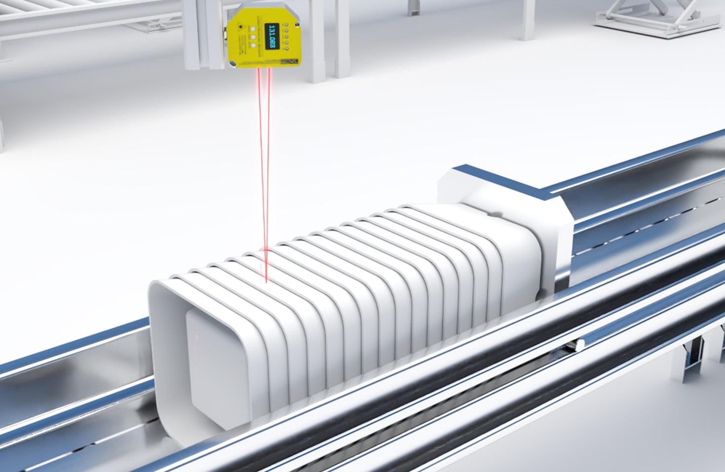
Selecting the correct cable requires a meticulous assessment of the application parameters. First, consider the electrical interface. Cables are designed for specific sensor families and protocols (e.g., analog voltage/current output, digital interfaces like RS-422, or proprietary bus systems). Using an incompatible cable will not work. Second, evaluate the cable length. Longer cables increase signal attenuation. Manufacturers provide specifications for maximum permissible cable length for given signal types; exceeding this limit degrades performance. For long runs, choosing a cable with lower capacitance per unit length is essential.
The operating environment dictates the required durability. Will the cable be stationary, in continuous flexing motion, or subjected to torsional twists? For continuous flexing, such as on a cable carrier, cables with specially stranded conductors and high-flex jackets are mandatory. Exposure to UV light, extreme temperatures, coolants, or cutting oils necessitates jackets with specific resistance ratings. Connectors are another vital consideration. They must match the sensor and amplifier ports perfectly, often requiring IP67 or higher ratings for dust and water ingress protection. Mismatched or poorly sealed connectors are a frequent point of failure.
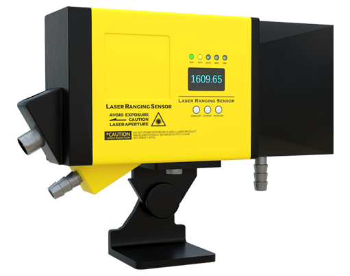
Installation and maintenance practices significantly impact cable lifespan. Adhere strictly to the specified minimum bending radius during routing. Use proper strain relief at both connection points to prevent pulling forces from transferring to the electrical terminations. In cable carriers, ensure correct clamping and avoid overfilling the tray. Cables should be routed away from high-power lines and sources of intense EMI whenever possible. Regular visual inspections for cracks, cuts, or deformation in the jacket can preempt catastrophic failures. Never attempt to repair a damaged shielded sensor cable with simple electrical tape; this compromises the shielding integrity. Instead, replace the cable or use manufacturer-approved repair kits.
A common pitfall is treating these specialized cables as commodity items. Opting for a generic, unshielded cable to save cost almost invariably leads to intermittent noise, data corruption, and costly downtime. The investment in a properly specified, high-quality laser displacement sensor cable is insignificant compared to the cost of production errors, recalibration labor, and lost throughput caused by sensor malfunctions.
In conclusion, the laser displacement sensor cable is a precision component that demands careful attention. By understanding its construction, meticulously matching it to the electrical, mechanical, and environmental requirements of the application, and following sound installation practices, engineers and maintenance personnel can ensure the longevity, accuracy, and reliability of their entire laser measurement system. This proactive approach safeguards the substantial investment in sensing technology and underpins consistent, high-quality automated operations.