Proximity sensor limit switches are critical components in industrial automation, providing precise position detection and control for machinery. Proper adjustment ensures reliable operation, prevents equipment damage, and maintains production efficiency. This guide details the professional methodology for adjusting these sensors, covering inductive, capacitive, and magnetic types commonly used in manufacturing and processing environments.
Before initiating any adjustment, adhere to strict safety protocols. De-energize and lock out the equipment (follow LOTO procedures). Visually inspect the sensor and its mounting for physical damage, corrosion, or loose connections. Verify the sensor's specifications, including sensing distance, output type (PNP/NPN, NO/NC), and supply voltage, against the machine's requirements. Incorrect voltage can cause immediate failure.
The core principle of adjustment is aligning the sensor's active sensing face with the target object (actuator) within its nominal sensing range. The target must be of the correct material and size as specified. For a standard cylindrical inductive sensor, the sensing distance is axial. For a capacitive sensor, the target's dielectric constant is crucial. Magnetic sensors require a specific pole alignment with the actuator magnet.
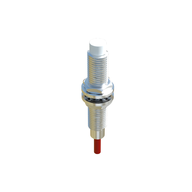
Adjustment Procedure:
1. Mounting and Preliminary Alignment: Securely mount the sensor in its bracket. Manually cycle the machine to bring the target into the expected detection position. Loosen the mounting hardware just enough to allow sensor movement.
2. Power Application and Signal Monitoring: Re-apply power to the control circuit only, ensuring machinery drives remain off. Connect a multimeter to the output signal wire or, preferably, monitor the indicator LED on the sensor itself. Most industrial proximity sensors feature a built-in LED that illuminates (typically yellow or green) when the target is detected.
3. Coarse Adjustment: Slowly move the sensor toward the target until the indicator LED activates. Note this position. Then, slowly retract the sensor away from the target until the LED just turns off. The optimal sensing point is typically midway between these ON and OFF points. This method accounts for switch hysteresis—the difference between the operate point and release point.
4. Fine-Tuning and Securing: With the sensor positioned at the calculated midpoint, carefully tighten the mounting hardware. Avoid overtightening, as this can shift the alignment or damage the housing. After securing, cycle the target past the sensor several times manually to verify consistent switching. The LED should activate and deactivate repeatably at the exact same position.
5. System Integration Test: Integrate the sensor signal back into the machine's PLC or control system. Perform a slow, controlled test cycle of the machine. Use the PLC programming software to monitor the input bit triggered by the sensor. Confirm the signal changes state at the precise mechanical position required by the application logic (e.g., cylinder fully extended, conveyor stop position).
Advanced Considerations and Troubleshooting:
Sensing Distance Derating: The rated sensing distance (Sn) is defined for a standard target. In practice, factors like target material, size, temperature, and voltage fluctuations require a "derating" factor. For reliable operation, the actual working distance should be 60-80% of the nominal Sn. Never operate at the absolute maximum range.
Environmental Interference: Metallic chips, dust, or other sensors in close proximity can cause false triggering. Ensure the sensor face is clean. Maintain a minimum distance (usually 2-3 times the sensor diameter) between adjacent sensors to prevent mutual interference. For capacitive sensors, guard against contamination from oils or moisture which alter the dielectric environment.
Output State Verification: Always confirm if your sensor is Normally Open (NO) or Normally Closed (NC), and if the wiring is sourcing (PNP) or sinking (NPN). An incorrect assumption here will lead to logic errors. Refer to the sensor's datasheet or body markings.
Common Faults: If adjustment fails, check for a worn or misaligned target, incorrect sensor type for the target material, damaged cable or connector, or electrical noise on the supply lines. A persistent "ON" state may indicate sensor failure or a short circuit. A persistent "OFF" state may indicate wiring issues, lack of power, or a sensor out of range.
Regular maintenance is essential. Periodically check the sensor's alignment and mounting stability, especially in high-vibration environments. Clean the sensing face to prevent buildup. Document adjustment settings for future reference. Properly adjusted proximity limit switches are a cornerstone of predictive maintenance, reducing unplanned downtime and ensuring long-term system integrity. By following this systematic approach, engineers and technicians can achieve optimal, repeatable performance from these vital automation components.