In industrial automation and control systems, proximity switches play a critical role in non-contact object detection. The reliability of these sensors is fundamentally dependent on correct wiring practices. This guide delves into the essential principles, standards, and procedures for connecting proximity switch sensor cables, ensuring optimal performance and system integrity.
Proximity switches, including inductive, capacitive, and photoelectric types, generate an electrical signal when a target object enters their sensing field. This signal is transmitted via the sensor's connection cable to a controller, such as a PLC (Programmable Logic Controller). The wiring process is not merely a physical connection; it is the vital link that ensures signal fidelity, power delivery, and protection against environmental interference.
The first step involves understanding the sensor's specifications. Most industrial proximity switches are categorized as either 2-wire, 3-wire, or 4-wire devices, each with distinct wiring schematics. Two-wire sensors are connected in series with the load, simplifying installation but often requiring careful consideration of residual current and voltage drop. Three-wire sensors are the most common, featuring separate wires for power supply positive (typically brown), power supply negative/ground (blue), and the switched output signal (black). Four-wire sensors usually provide both Normally Open (NO) and Normally Closed (NC) output signals.
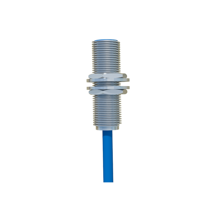
Key wiring considerations include:
1. Power Supply Compatibility: Always match the sensor's operating voltage (e.g., 10-30V DC, 20-250V AC) with the control system's power source. Incorrect voltage can cause immediate failure or erratic behavior.
2. Output Configuration: Determine if the output is sinking (NPN) or sourcing (PNP). Sinking (NPN) switches connect the load to the positive supply, allowing current to flow into the switch to the negative. Sourcing (PNP) switches connect the load to ground, with current flowing out of the switch. Mismatching this with the PLC input type is a frequent installation error.
3. Shielding and Cable Routing: Sensor cables are susceptible to electromagnetic interference (EMI) from motors, drives, and power lines. Using shielded cables and properly grounding the shield at only one end (typically the control panel end) is paramount. Cables should be routed away from high-voltage power lines, preferably in separate conduits or trays.
4. Connection Integrity: Use appropriate wire gauges as per current ratings. Ensure terminals are tightened to the manufacturer's specified torque. Loose connections lead to increased resistance, heat generation, and signal loss. For harsh environments, specify cables with robust insulation and high IP (Ingress Protection) ratings.
5. Circuit Protection: Incorporate fuses or circuit breakers in the supply line to protect against short circuits. In DC circuits, adding a flyback diode across the load (especially inductive loads like relays) suppresses voltage spikes that can damage the sensor's solid-state output.
The installation procedure should follow a disciplined sequence: de-energize the control circuit, verify sensor type and part number, strip cable ends to the correct length, crimp or solder terminals securely, connect wires to the correct terminals as per the datasheet diagram, secure cable strain relief, and finally, perform a functional test before powering the entire system.
Post-installation, troubleshooting common wiring issues is a necessary skill. Symptoms like no output signal, intermittent operation, or sensor damage often trace back to wiring faults. Use a multimeter to check for correct supply voltage at the sensor terminals, continuity of cables, and proper output switching. Remember that inductive proximity sensors require a ferrous metal target, while capacitive sensors can detect non-metallic materials; an incorrect sensor type for the application will fail regardless of wiring correctness.
In summary, the connection wiring for proximity switch sensors is a foundational aspect of industrial electrical engineering. Adherence to manufacturer guidelines, industry standards like IEC 60947-5-2, and robust installation practices directly translates to enhanced machine safety, reduced downtime, and long-term system reliability. A meticulously wired sensor network forms the reliable nervous system of any automated process.