In industrial automation and control systems, proximity sensors are indispensable components for detecting the presence or absence of objects without physical contact. Among various wiring configurations, series connection of proximity sensors is a common practice to optimize control logic, reduce wiring complexity, and enhance system reliability. This article provides a detailed, step-by-step guide on wiring proximity sensors in series, tailored for electrical engineers and technicians working in industrial settings.
Understanding Series Wiring Basics
Series wiring involves connecting multiple proximity sensors in a sequence where the same current flows through each sensor. This configuration is typically used when sensors need to act as a logical "AND" function—meaning all sensors must be triggered for the circuit to activate. For instance, in a safety interlock system, multiple sensors may be wired in series to ensure all guards are closed before machinery starts. Before proceeding, it’s crucial to verify sensor compatibility. Most inductive or capacitive proximity sensors with NPN (sinking) or PNP (sourcing) outputs can be wired in series, provided they share the same voltage rating (e.g., 24V DC). Always consult the manufacturer’s datasheet to confirm specifications.
Step-by-Step Wiring Procedure
1. Power Supply Preparation: Begin by selecting a suitable DC power supply matching the sensors’ voltage requirements. For example, use a 24V DC supply for sensors rated at 10-30V DC. Ensure the power supply is disconnected during wiring to prevent electrical hazards.
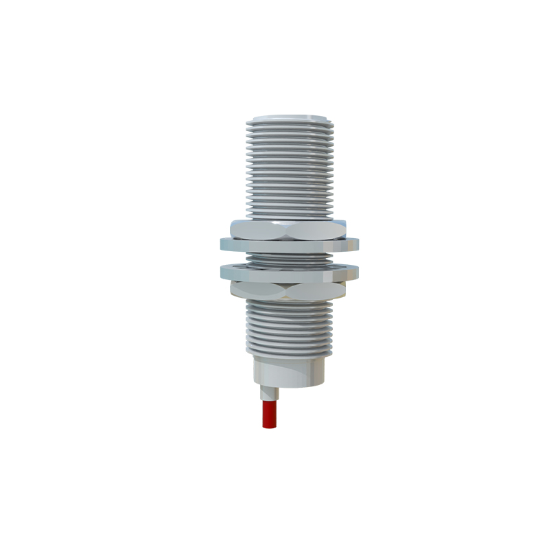
2. Identify Sensor Terminals: Typically, proximity sensors have three wires: brown (positive), blue (negative), and black (output). For series wiring, focus on the output and common wires. In a series circuit, the output of one sensor connects to the input of the next.
3. Connect Sensors in Series: For NPN sensors (sinking output), wire the brown (positive) wires of all sensors to the power supply’s positive terminal. Connect the blue (negative) wires to the power supply’s negative terminal. Then, link the black (output) wire of the first sensor to the brown (positive) wire of the second sensor, and continue this pattern for additional sensors. The final sensor’s black output wire connects to the load (e.g., PLC input or relay). For PNP sensors (sourcing output), reverse the logic: connect blue wires to positive and brown wires to negative, while chaining outputs similarly.
4. Load Integration: Connect the series circuit’s end to the load device. If using a PLC, ensure the input module matches the sensor type (NPN/PNP). Add a protective fuse or circuit breaker near the power supply to prevent overcurrent damage.
5. Testing and Validation: After wiring, power on the system and test each sensor individually. Use a multimeter to check voltage drops across sensors when triggered. In series, if any sensor fails or is not activated, the circuit remains open, and the load won’t engage—this is key for fault detection.
Considerations for Reliable Operation
- Voltage Drop: Series wiring can cause cumulative voltage drops across sensors, potentially reducing signal strength. Calculate total voltage drop by summing individual drops (usually listed in datasheets). Ensure the final voltage at the load meets minimum requirements (e.g., above 18V for a 24V system).
- Current Limitations: Verify that the power supply can handle the combined current draw of all sensors. Exceeding current ratings may lead to overheating or sensor malfunction.
- Shielding and Noise: In environments with electromagnetic interference, use shielded cables and ground the shield properly to prevent false triggering. Keep sensor cables away from high-voltage lines.
- Maintenance and Troubleshooting: Label each sensor and connection point clearly for easy identification. Common issues in series circuits include open circuits from a single faulty sensor or wiring errors. Use diagnostic tools like continuity testers to isolate problems.
Applications in Industrial Systems
Series wiring is ideal for applications requiring multi-point confirmation. Examples include conveyor belt systems where sensors detect objects at sequential stations, or robotic cells where multiple safety sensors must be engaged before operation. In automotive assembly lines, proximity sensors wired in series ensure components are correctly positioned before welding or painting processes. This method not only simplifies control logic but also enhances safety by preventing partial system activation.
Conclusion
Wiring proximity sensors in series is a straightforward yet powerful technique for industrial control systems. By following proper procedures and accounting for electrical characteristics, engineers can build robust circuits that improve efficiency and safety. Always prioritize manufacturer guidelines and regular maintenance to ensure long-term performance. As automation evolves, mastering such wiring methods remains essential for optimizing modern manufacturing workflows.