In industrial automation and electrical systems, proximity sensor lights are critical indicators of operational status. A common yet often misunderstood issue is when the proximity sensor's indicator light flashes continuously. This persistent flashing is not merely an annoyance; it is a diagnostic signal conveying specific information about the sensor's state, the target object, or the connected system. Understanding the root causes is essential for maintaining system integrity and preventing downtime.
Fundamentally, a proximity sensor detects the presence or absence of a metallic or non-metallic object within its sensing range without physical contact. The integrated LED, typically in red, green, or amber, provides visual feedback. A stable, continuous light usually signifies normal operation—either target detected or not detected, depending on the sensor's configuration (Normally Open or Normally Closed). Flashing, however, indicates an abnormal condition or a specific mode of operation.
The primary causes of a flashing proximity sensor light can be categorized as follows:
1. Power Supply Issues: This is the most frequent culprit. Voltage fluctuations, insufficient current, or unstable power can cause the sensor to reset intermittently, resulting in a flashing LED. Check if the supply voltage matches the sensor's rated voltage (e.g., 10-30V DC). Undervoltage can prevent proper operation, while overvoltage might trigger internal protection circuits. Ensure the power supply unit (PSU) has adequate capacity and stable output. Ripple or noise on the DC line, often from nearby variable frequency drives (VFDs) or large inductive loads, can also induce erratic behavior. Using a shielded cable and proper grounding is crucial.
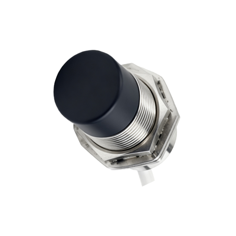
2. Incorrect Wiring or Connection Faults: Loose connections, corroded terminals, or damaged cables can create intermittent contact. Verify all wiring against the manufacturer's datasheet. For a 3-wire DC sensor, confirm the correct connection of Brown (V+), Blue (V- or 0V), and Black (output). A loose connection in the load circuit (e.g., to a PLC input or relay) can also cause the sensor to behave unpredictably. Ensure wire ferrules are properly crimped and terminal screws are tightened to the specified torque.
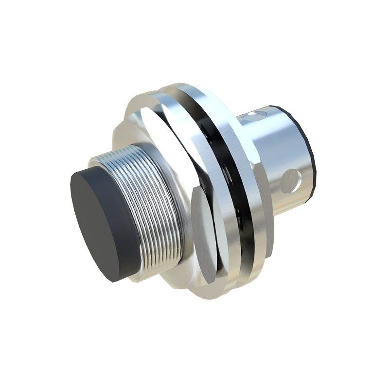
3. Sensor Misalignment or Target Problems: The flashing may indicate that the target is at the very edge of the sensor's effective sensing range. The sensor might be detecting and losing the target rapidly due to vibration, misalignment, or an irregular target surface. Ensure the target material, size, and approach angle are within specifications. For inductive sensors, the target must be a ferrous or non-ferrous metal of sufficient size. For capacitive sensors, changes in the target's dielectric constant or environmental factors like humidity can cause unstable sensing.
4. Output Overload or Short Circuit: If the sensor's output transistor is connected to a load exceeding its maximum current rating (e.g., directly driving a large contactor coil without an interposing relay), it may enter a protective state. Many modern sensors have short-circuit and overload protection. When activated, this protection often causes the LED to flash in a specific pattern (e.g., two short flashes followed by a pause). Consult the manual for blink code definitions.
5. Environmental Interference: Strong electromagnetic interference (EMI) from motors, welding equipment, or radio transmitters can disrupt the sensor's oscillator circuit (in inductive models) or signal processing. Ensure the sensor is rated for the industrial environment (IP rating) and consider using sensors with built-in immunity or metal housings. Excessive ambient temperature beyond the sensor's operating range can also lead to unstable performance and flashing warnings.
6. Internal Fault or End-of-Life: Although robust, sensors can fail internally due to component aging, moisture ingress, or physical damage. A specific, unchangeable flash pattern often indicates a permanent internal fault. Refer to the product manual; a sequence like one long flash and two short flashes has a defined meaning.
7. Special Function Mode: Some programmable or intelligent sensors use LED flashing sequences to indicate setup modes, teach-in procedures, or diagnostic states. This is normal during configuration.
Troubleshooting Procedure:
Step 1: Isolate the sensor. Disconnect the output load and observe the LED. If flashing stops, the issue is likely an overload or problem in the load circuit.
Step 2: Measure the supply voltage at the sensor's terminals with a multimeter under load, watching for dips or noise.
Step 3: Inspect all physical connections, cables, and the target alignment.
Step 4: Substitute with a known-good sensor of the same model. If the problem resolves, the original sensor is faulty.
Step 5: Always consult the specific product manual for diagnostic LED codes.