In the complex and demanding world of industrial automation, the accurate measurement of electrical current is paramount for system control, safety, and efficiency. While dedicated current transformers (CTs) and Hall-effect sensors are the traditional go-to solutions, a sophisticated application of proximity switch sensors has emerged as a viable method for indirect current sensing in specific scenarios. This article delves into the principles, methodologies, and practical considerations of using proximity switch sensors to infer current levels.
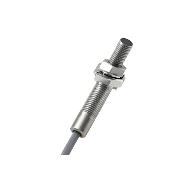
The fundamental principle behind a standard inductive proximity switch is the detection of metallic objects through the disturbance of an electromagnetic field generated by an oscillator coil. It does not directly measure electrical parameters like current or voltage. Therefore, the concept of a proximity sensor "measuring current" is not direct but rather an indirect inference based on a secondary effect: the magnetic field generated by the current-carrying conductor.
When an electrical current flows through a conductor, it generates a proportional magnetic field around it, as described by Ampère's law. A standard inductive proximity sensor can be sensitive to this magnetic field, especially if the sensor's internal coil design and operating frequency are considered. The core technique involves positioning the proximity sensor in close proximity to a specific component whose magnetic properties change predictably with the current flowing through it. The most common implementation involves monitoring the state of a relay or a contactor.
Consider a scenario where a high-current contactor is used to switch a motor load. The contactor's coil, when energized, creates a magnetic field that pulls in the armature, closing the main power contacts. A proximity sensor can be mounted to detect the physical position of this armature or the plunger within the contactor coil. When the coil is de-energized (zero current), the armature is in its retracted position. When sufficient current flows through the coil to energize the contactor, the armature moves to its engaged position. The proximity sensor detects this metallic movement. Thus, the sensor's output signal (ON/OFF) indicates whether the coil current is above a certain threshold required for actuation. This provides a binary indication of current presence or absence in the control circuit, not a proportional analog value.
For a more nuanced, though still non-precise, measurement, some setups use the magnetic field directly. If a conductor carrying a large alternating current (AC) is routed in a specific loop or near a ferrous element, the resulting alternating magnetic field can induce effects detectable by certain proximity sensors. For instance, the sensor might be positioned near a specially designed ferrous "target" that vibrates or changes its electromagnetic characteristics minutely under the influence of the AC magnetic field. The sensor's internal circuitry might interpret these changes as a fluctuating signal. However, this method is highly susceptible to interference, requires careful calibration for a specific setup, and does not yield a calibrated amperage reading. It is more suited for detecting gross over-current conditions or current presence rather than precise measurement.
The critical distinction lies in the output. A true current sensor provides a continuous analog signal (e.g., 4-20mA, 0-10V) or a digital value proportional to the measured current. A proximity switch used in this indirect manner typically provides a discrete, binary PNP or NPN output. It signals a state: current above a threshold (ON) or below a threshold (OFF). This is why its application is perfect for state monitoring and control interlocking rather than for process control or energy metering.
Key advantages of this approach include robustness and simplicity. Proximity sensors are inherently rugged, designed for harsh industrial environments with vibration, dust, and moisture. Using them to monitor a contactor's state leverages their durability. It also adds a layer of diagnostic information; the control system knows not just that a command was sent to the contactor coil, but that the contactor physically responded. This can diagnose issues like a failed coil, mechanical binding, or loss of control power.
However, significant limitations must be acknowledged. The measurement is indirect, binary, and non-isolated. It infers current from a mechanical position, not from the electrical parameter itself. Accuracy for determining exact current values is poor to non-existent. The method is highly application-specific and depends on the consistent magnetic and mechanical behavior of the component being monitored (like the contactor). It cannot be used for measuring load current directly on a busbar or cable without extensive and unreliable customization.
In conclusion, while proximity switch sensors are not designed or recommended for direct, precise electrical current measurement, they can be ingeniously employed to infer the operational state of current-driven devices like contactors and relays. This provides valuable binary feedback for control and diagnostic purposes in industrial panels and machinery. For any requirement involving accurate, proportional, or isolated current measurement for protection, control, or monitoring, dedicated current sensors remain the essential and correct choice. The use of proximity sensors