In the world of industrial automation and machinery control, the reliable connection between proximity sensors and proximity switches is fundamental. While the terms are sometimes used interchangeably, understanding their distinct roles is the first step to a successful installation. A proximity sensor is the sensing element that detects the presence or absence of an object without physical contact, typically using inductive, capacitive, or magnetic principles. A proximity switch, often referred to simply as a "switch" or "controller" in this context, is the electronic unit that processes the sensor's signal and provides a usable output, such as a relay contact or a solid-state signal, to control other devices like PLCs, motors, or indicators.
The connection process begins long before any wires are touched. Safety is paramount. Always ensure the entire system is powered down and locked out according to standard safety procedures. Verify the voltage ratings of both the proximity sensor and the switch. Mismatched voltages are a common cause of immediate failure. Gather the necessary tools: appropriate wire strippers, screwdrivers, and possibly a multimeter for verification.
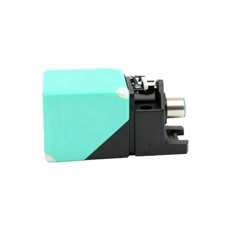
Most modern proximity sensors are categorized as either 2-wire, 3-wire, or 4-wire devices. The 3-wire type is most prevalent in DC applications. It consists of a brown wire (typically for positive supply +V), a blue wire (for negative supply or common 0V), and a black wire (the output signal). The proximity switch must be compatible with this configuration. It provides the power supply (e.g., 24V DC) on two terminals and receives the sensor's output signal on another.
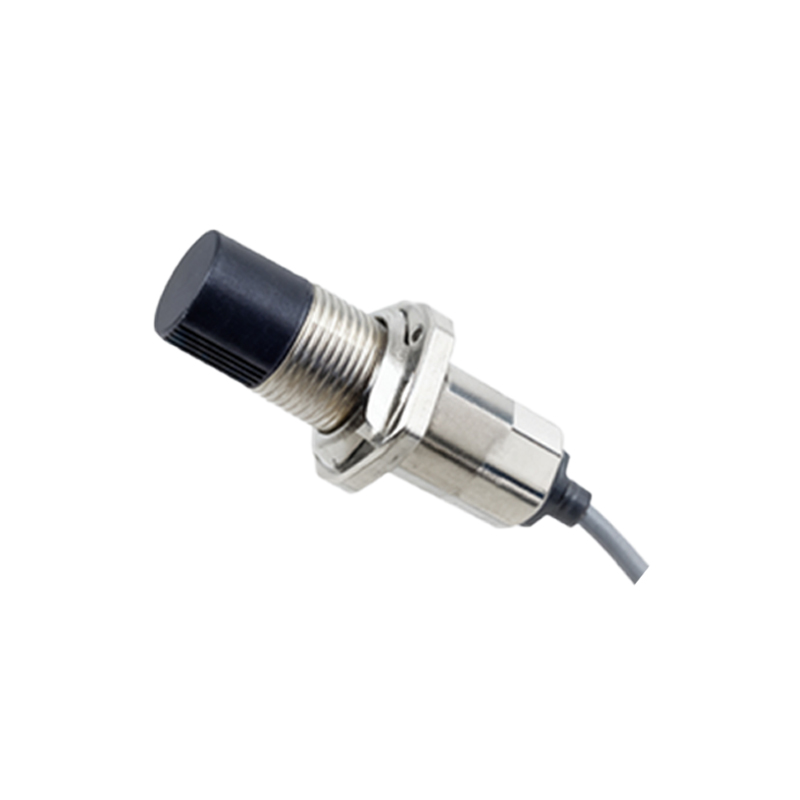
Here is a typical step-by-step procedure for connecting a 3-wire DC inductive proximity sensor to a compatible proximity switch module:
1. Identify Terminals: Locate the terminal markings on both devices. The sensor's cable will be color-coded (Brown, Blue, Black). The switch unit will have clearly labeled terminals, such as +V (or L+), 0V (or L- or M), and IN (or Input).
2. Run and Prepare Wiring: Run a suitable multi-core cable from the sensor location to the switch location. Strip the insulation from the ends of each wire to the length specified by the terminal block.
3. Connect Power to the Sensor: Connect the brown wire from the sensor to the +V terminal on the switch. Connect the blue wire from the sensor to the 0V terminal on the switch. This provides the operating power to the sensor.
4. Connect the Output Signal: Connect the black wire (output) from the sensor to the IN (input) terminal on the proximity switch.
5. Secure and Organize: Tighten all terminal screws securely to prevent loose connections, which cause intermittent faults. Use cable ties to neatly route wires away from moving parts or heat sources.
For a 2-wire AC sensor, the connection is simpler but requires careful attention to load rating. The two wires are connected in series with the AC power supply and the load (the input of the switch). The switch's input must be rated to handle the sensor's leakage current when in the "off" state.
After connections are made, a systematic verification is crucial. Restore power cautiously. Observe the indicator LEDs, which are present on most sensors and switches. A typical inductive sensor will have an LED that lights when a metal target is within its sensing range. The proximity switch will also have an indicator showing the status of its input. Bring a target (e.g., a piece of metal) close to the active face of the sensor. You should see the sensor's LED illuminate and, simultaneously, the input indicator on the switch should activate. The switch's output relay should energize or its signal should change state, which you can test with a multimeter or by observing the controlled device.
Troubleshooting common issues often involves this LED feedback. If the sensor LED does not light, check the power supply connections and voltage. If the sensor LED lights but the switch input does not activate, check the wiring of the output (black) wire and the input circuit of the switch. Ensure the sensing distance is correct and the target material is suitable (for inductive sensors, only metals are detected). Electrical noise in industrial environments can cause erratic behavior. Use shielded cable for long runs, connect the shield to ground at one end only (usually at the switch cabinet), and keep sensor cables away from high-power motor leads.
A correct and secure connection ensures not only immediate functionality but also long-term stability, reducing machine downtime and maintenance costs. This physical link is the critical bridge that allows the precise, non-contact detection of the sensor to be translated into a robust control action by the switch, forming the backbone of countless automated processes.