Proximity sensors are indispensable components in modern industrial automation, robotics, and smart systems. Their ability to detect the presence or absence of an object without physical contact makes them crucial for tasks ranging from object counting and position sensing to safety interlocks and level detection. The effectiveness of a proximity sensor system hinges not only on the sensor itself but also on its supporting application circuit. This article delves into the core circuit designs for various types of proximity sensors, providing a practical guide for engineers.
The most common types are inductive, capacitive, and photoelectric proximity sensors. Each type requires a tailored circuit approach.
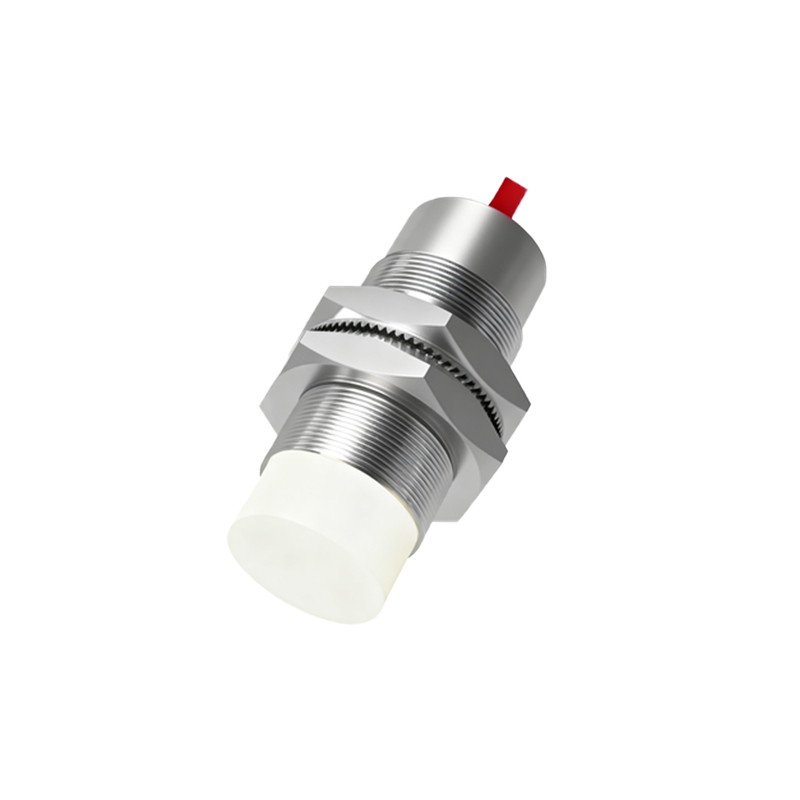
1. Inductive Proximity Sensor Circuits
Inductive sensors detect metallic objects. The core is an LC oscillator circuit. A typical application circuit includes the sensor coil (L), a capacitor (C) forming the tank circuit, an oscillator (often using a dedicated IC like TCA505 or a transistor-based design), a demodulator, a Schmitt trigger, and an output stage.
Basic Operation: The oscillator generates a high-frequency electromagnetic field from the coil. When a metal object enters this field, eddy currents are induced, causing a change in the oscillator's amplitude or frequency. The demodulator converts this change into a DC voltage shift. The Schmitt trigger provides a clean, hysteresis-based digital output (e.g., NPN or PNP transistor, or a relay driver) immune to noise.
Key Circuit Considerations: Shielding, cable length compensation, and protection against voltage transients are vital. A simple circuit might integrate a series resistor for current limiting and a flyback diode for inductive load protection on the output. For 3-wire DC sensors, ensuring correct common (COM) connection to the power supply negative or positive is critical.
2. Capacitive Proximity Sensor Circuits
These sensors detect both metallic and non-metallic materials (plastics, liquids, wood) by sensing changes in capacitance. The circuit resembles an inductive one but operates with a different sensing element.
Basic Operation: The sensor plate forms one plate of a capacitor, with the target object acting as the other plate (or altering the dielectric). This forms part of an RC or LC oscillator circuit. The presence of a target increases the capacitance, shifting the oscillation characteristics. This shift is detected, typically by a change in the charge/discharge time constant measured by a comparator or dedicated IC (e.g., TTP223 for simple touch/proximity).
Key Circuit Considerations: Sensitivity adjustment via a potentiometer is common to tune for different materials. These circuits are highly susceptible to environmental humidity and contaminants. Guard rings (driven shields) in the circuit design are often used to focus the sensing field and reduce stray capacitance effects. Proper grounding and shielding of the connecting cable are essential.
3. Photoelectric Sensor Circuits
Photoelectric sensors use light beams (infrared, visible, laser) and consist of an emitter (LED/laser diode) and a receiver (phototransistor, photodiode). Circuits are divided into emitter and receiver sides.
Emitter Circuit: A constant current driver circuit is used for the LED to ensure stable light intensity, often using a transistor or an op-amp with a current-sensing resistor. Modulation of the LED at a specific frequency (e.g., several kHz) is standard practice to make the sensor immune to ambient light.
Receiver Circuit: The phototransistor converts modulated light into a small current. This signal passes through a transimpedance amplifier (to convert current to voltage) and then a band-pass filter or a tuned amplifier locked to the modulation frequency. This stage rejects DC light (like sunlight) and low-frequency noise. The signal is then rectified, compared to a threshold by a comparator, and fed to a digital output stage.
Key Circuit Considerations: Alignment, lens cleanliness, and avoiding optical crosstalk are system-level concerns. Circuit-wise, careful PCB layout to separate analog sensitive receiver parts from digital noise sources is crucial. For long-range or analog output models, amplification and noise filtering stages become more complex.
Universal Application Circuit Elements:
Regardless of type, most sensor modules incorporate these elements:
Power Supply Regulation & Filtering: A local regulator (e.g., 78L05) and decoupling capacitors ensure stable voltage for the sensitive oscillator/comparator circuits.
Output Interface: This can be an NPN/PNP open-collector transistor for PLC compatibility, a solid-state relay, or a line driver (RS-422). Always include a clamping diode for inductive loads (relays, solenoids) and a current-limiting resistor for LED indicators.
Protection Circuits: Reverse polarity protection (using a diode), overvoltage protection (TVS diodes), and output short-circuit protection are industry