In industrial automation and control systems, 24V DC proximity sensors are ubiquitous components, prized for their reliability, long service life, and non-contact detection capabilities. Correct wiring is fundamental to ensuring their optimal performance, safety, and integration with Programmable Logic Controllers (PLCs) or other control devices. This guide provides a comprehensive, step-by-step approach to wiring a standard 3-wire DC proximity sensor, covering essential principles, tools, and common pitfalls to avoid.
Before beginning any wiring procedure, the paramount rule is safety. Always disconnect and lock out/tag out (LOTO) the power source to the circuit. Verify the voltage is off using a multimeter. Gather the necessary tools: appropriate wire strippers, crimping tools, screwdrivers, and a digital multimeter. Most importantly, carefully read the sensor's datasheet and manual. The information on the nameplate and in the documentation is definitive—it specifies the sensor's type (PNP or NPN), sensing distance, output configuration, voltage range, and current rating.
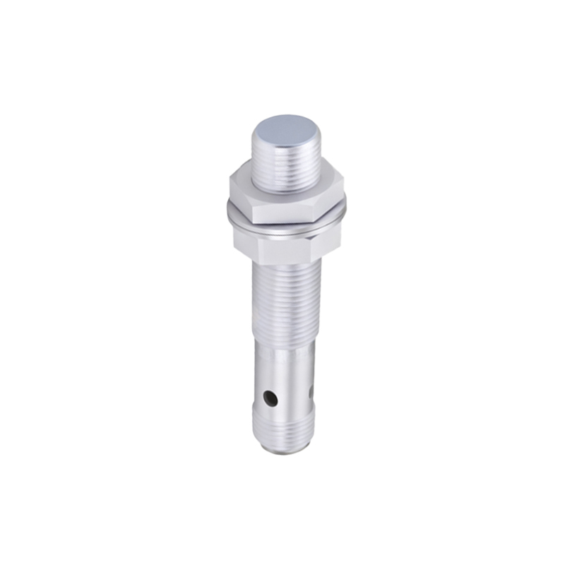
Understanding the core terminology is crucial. A 24V DC proximity sensor typically has three wires, color-coded according to international standards (often brown, blue, and black). The Brown wire is universally connected to the positive DC supply voltage (+24V). The Blue wire is always connected to the common negative or 0V DC supply (DC Common). The third wire, often Black, is the signal output wire. Its behavior defines the sensor as either PNP or NPN.
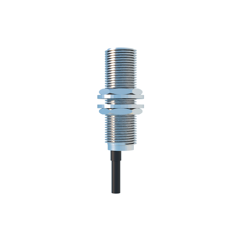
PNP (Sourcing) Sensor: In a PNP sensor, the black output wire acts as a source of positive current. When the sensor detects a target, it switches internally, connecting the black wire to the internal +24V (brown wire). Thus, the output provides +24V to the load (e.g., a PLC input).
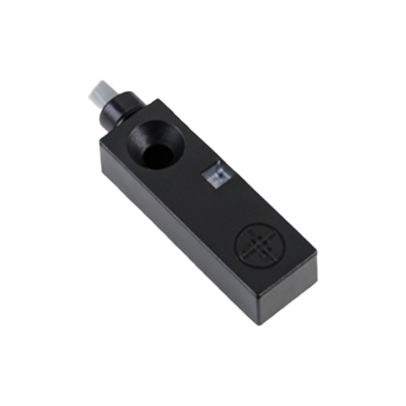
NPN (Sinking) Sensor: In an NPN sensor, the black output wire acts as a sink for current. When activated, it switches internally to connect the black wire to the internal 0V (blue wire). Thus, it provides a path to ground for the load.
The load (your PLC input module) must be compatible. A PNP sensor requires a PLC input card configured to accept a "sourcing" signal (often labeled as "sink/source" or "positive logic"). An NPN sensor requires a "sinking" input card configuration.
Step-by-Step Wiring Procedure for a 3-Wire 24V Sensor:
1. Power Isolation: Ensure the 24V DC power supply is completely disconnected and secured.
2. Prepare Wires: Strip a short length of insulation from the ends of your sensor cable and the power/signal cables from your control panel. Use ferrules for a professional, secure connection if possible.
3. Connect Power Wires:
Connect the sensor's Brown wire to the +24V DC terminal of your power supply.
Connect the sensor's Blue wire to the 0V DC (Common) terminal of your power supply.
Ensure these connections are tight and secure.
4. Connect the Signal Output Wire:
For a PNP Sensor: Connect the sensor's Black wire to the designated input terminal on your PLC. The common side of that PLC input channel must be connected to 0V DC.
For an NPN Sensor: Connect the sensor's Black wire to the designated input terminal on your PLC. The common side of that PLC input channel must be connected to +24V DC.
Critical Note: Always confirm your PLC input module's wiring diagram. Some modules have a common terminal that must be wired to either +24V or 0V to match the sensor type.
5. Routing and Protection: Route the sensor cable away from high-voltage power cables and sources of electromagnetic interference (like motor drives) to prevent false triggering. Use cable conduits or trays for physical protection.
6. Pre-Power Check: Double-check all connections against the datasheet and your wiring diagram. Verify there are no loose strands that could cause short circuits.
7. Apply Power and Test: Restore power to the 24V DC supply. Observe the sensor's indicator LED (if present). It may be solid or blinking when no target is present. Bring the specified target material (usually ferrous metal for inductive sensors) within the sensing range. The LED state should change, indicating activation. Use your multimeter to measure the voltage between the black signal wire and