In industrial automation and precision measurement, laser displacement sensors are indispensable tools. Their ability to provide non-contact, high-accuracy distance measurements makes them vital for applications ranging from thickness gauging and vibration analysis to part profiling and level detection. However, the full potential of these sophisticated devices can only be realized with correct and reliable electrical wiring. Improper connections can lead to inaccurate readings, sensor damage, or even system failure. This guide provides a comprehensive, step-by-step overview of laser displacement sensor wiring, focusing on best practices for electrical engineers and technicians.
Before handling any wiring, the paramount rule is safety. Always disconnect power to the entire system. Consult the specific sensor's datasheet and installation manual—models from Keyence, Panasonic, Omron, or Micro-Epsilon, while sharing principles, may have unique pin assignments, voltage requirements, and cable specifications. Gather necessary tools: appropriate wire strippers, crimping tools, screwdrivers, and a multimeter for verification.
Most industrial laser displacement sensors utilize a standardized cable system, typically a pre-molded cable with a connector that mates directly to the sensor head. The other end is often a flying lead with individual color-coded wires. The core wiring involves connecting these leads to a controller, PLC (Programmable Logic Controller), or dedicated amplifier unit.
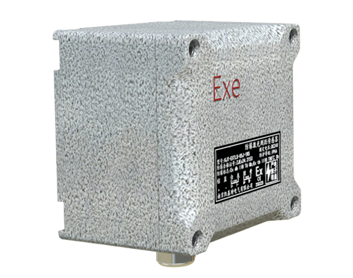
A typical wiring configuration for a standard DC sensor includes the following connections:
1. Power Supply (Vcc and GND): This is the foundation. Most sensors operate on a 12-24V DC supply. The red wire (or brown, per IEC standards) is usually for Vcc (+), and the blue wire is for 0V or GND (-). It is critical to observe polarity. An incorrect connection can permanently damage the internal circuitry. Ensure the power supply is stable, regulated, and within the sensor's specified range. Noise from the power line is a common source of measurement instability; using a separate, clean power supply for sensitive measurement equipment is often recommended.
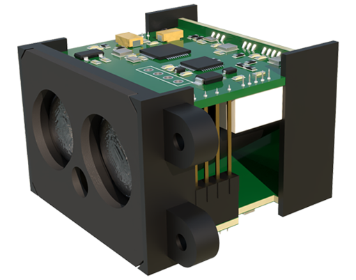
2. Output Signal: This is how the sensor communicates its measurement. The most common types are:
* Analog Output (Voltage or Current): A black or white wire typically carries an analog signal, such as 0-10V or 4-20mA, proportional to the measured distance. For voltage output, the return path is usually the common GND. For 4-20mA current output, it forms a loop with the receiving device. Wiring for current output must ensure the loop is complete and the load impedance is within specified limits.
* Digital Output (NPN or PNP): Often a black wire for the switched output. NPN (sinking) and PNP (sourcing) are two transistor-based output types. Their wiring is fundamentally different and must match the input type of your PLC/counter.
* For an NPN sensor (common negative switch), the output wire switches the load to GND. The load (e.g., PLC input) is connected between Vcc and the sensor's output wire.
* For a PNP sensor (common positive switch), the output wire switches the load to Vcc. The load is connected between the sensor's output wire and GND.
* Digital Communication: Higher-end sensors may offer RS-232, RS-485, or Ethernet/IP outputs. These use multiple wires (Tx, Rx, Data+, Data-, etc.) and require careful pairing and termination, especially for RS-485 networks.
3. Control Inputs: Some sensors feature discrete input wires (often orange or gray) for functions like external triggering (TEACH), output hold, or reset. These are typically connected to a PLC's digital output or a physical switch.
The Wiring Procedure:
1. Preparation: Identify all wires using the manual. Plan the cable route, keeping sensor cables away from high-voltage power lines, motor drives, or welding equipment to avoid electromagnetic interference (EMI). Use conduit or shielded cable if running near noise sources.
2. Connection: Strip a minimal amount of insulation from each wire. Use ferrules for a clean, secure connection if using screw terminals on a PLC. Connect the power wires first (Vcc and GND), ensuring they are tight.
3. Shielding: The cable shield (usually a bare braid or foil with a drain wire) is crucial for noise immunity. Connect the shield to a stable earth ground (PE) at *one end only*, typically at the controller/PLC side. Grounding both ends can create ground loops, inducing noise. Connect the drain wire to the dedicated grounding terminal.
4. Output & Inputs: Connect the analog or digital output wire to the correct terminal on your receiving device. Connect any control input wires as required by your application.
5. Verification: Before applying power, double-check every connection against the wiring diagram. Use a multimeter in continuity mode to check for accidental shorts between wires, especially between Vcc and GND. Visually inspect for stray wire strands.
Post-Wiring Check and Troubleshooting:
Apply power. Observe the sensor's indicator LED; it should show normal operation (e.g., steady green). Test the measurement by placing a target within range. Use a multimeter to read the analog output or monitor the digital signal on your PLC.
Common wiring-related issues include:
* No Output/No Power: Verify power supply voltage and polarity. Check for blown fuses.
* Unstable or Noisy Readings: This is often an EMI or grounding issue. Verify the shield is properly grounded at one point. Increase separation from noise sources. Ensure the power supply is clean.
* Incorrect Output Value: Verify the output scaling (e.g., 0-10V corresponding to 50-100mm). Check for wiring errors between NPN/PNP and the PLC input type.
In conclusion, meticulous wiring is not merely an installation step but a critical factor in ensuring the reliability, accuracy, and longevity of a laser displacement measurement system. By adhering to the manufacturer's specifications, implementing robust grounding and shielding practices, and methodically verifying connections, engineers can eliminate a primary source of field failures and ensure these precision instruments perform to their full capability.