Infrared proximity sensors are widely used in industrial automation, robotics, and safety systems due to their non-contact detection capabilities. Understanding the interface specifications is crucial for seamless integration and optimal performance. This guide provides a comprehensive overview of common infrared proximity sensor interfaces, covering electrical connections, communication protocols, and practical implementation tips.
Infrared proximity sensors typically operate by emitting infrared light and measuring the reflection from nearby objects. The interface components include power supply pins, output signals, and optional communication lines. Most sensors require a DC power supply, commonly ranging from 5V to 24V, depending on the model. It is essential to verify the voltage ratings to prevent damage. The output can be analog (e.g., 0-10V or 4-20mA) or digital (e.g., NPN/PNP open collector or push-pull). Analog outputs provide continuous distance measurements, while digital outputs offer simple on/off detection based on a threshold.
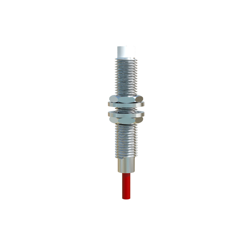
For digital interfaces, NPN and PNP configurations are prevalent. NPN sensors sink current to ground when activated, suitable for PLCs with sinking input modules. PNP sensors source current to the load, compatible with sourcing inputs. Always check the sensor datasheet for correct wiring to avoid reverse polarity or short circuits. Additionally, some advanced sensors feature IO-Link, RS-485, or I2C interfaces for digital communication. IO-Link enables parameter configuration, diagnostics, and real-time data exchange, enhancing flexibility in smart factories. RS-485 supports multi-drop networks for long-distance communication, while I2C is ideal for short-range board-level connections.
When interfacing with microcontrollers or PLCs, consider signal conditioning. For analog outputs, use ADC modules with appropriate resolution and filtering to reduce noise. Digital outputs may require pull-up resistors or optocouplers for isolation in noisy environments. Ensure the sensor’s response time aligns with system requirements; typical response times range from 0.5ms to 10ms. Environmental factors like ambient light, dust, or reflective surfaces can affect accuracy, so select sensors with modulated IR signals or built-in compensation.
Installation guidelines include proper alignment, avoiding obstructions, and maintaining clean lenses. Regular calibration using manufacturer-recommended procedures ensures consistent performance. For troubleshooting, monitor output signals with oscilloscopes or multimeters, and refer to error codes in programmable sensors. Always follow ESD precautions during handling to prevent electrostatic damage.
In summary, successful integration of infrared proximity sensors hinges on understanding interface specifications, matching electrical characteristics, and adhering to best practices. By selecting the right interface and implementing robust connections, engineers can enhance system reliability and efficiency in diverse applications.