In the realm of industrial automation, the reliable detection of objects without physical contact is paramount. Among the myriad of sensing solutions available, the M30 3-wire proximity switch stands as a workhorse, renowned for its robustness, versatility, and straightforward integration. This guide delves into the technical specifications, operating principles, wiring configurations, and key application considerations for this ubiquitous sensor.
Understanding the M30 Form Factor
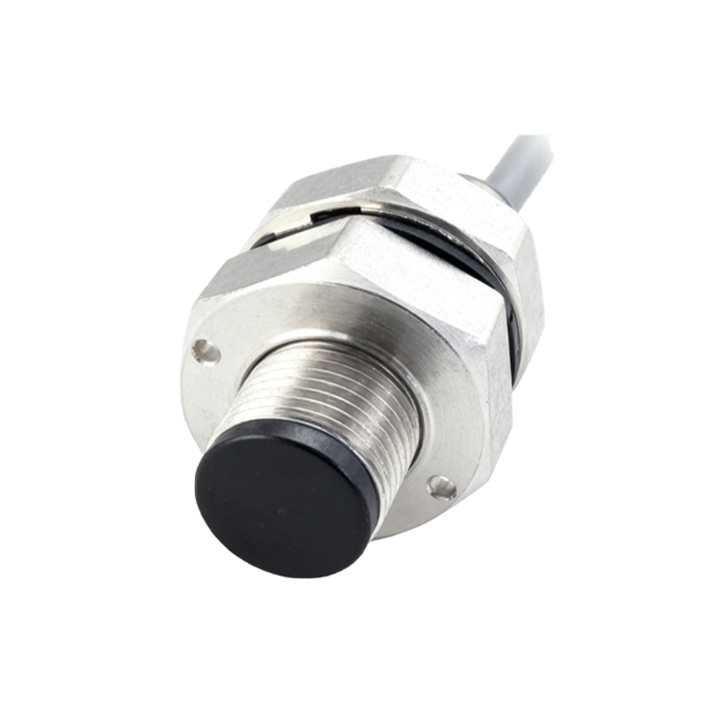
The "M30" designation refers to the sensor's threaded barrel housing, which is 30 millimeters in diameter. This standardized size allows for easy installation in machined holes or mounting brackets, providing a secure and stable sensing position. The housing is typically constructed from nickel-plated brass, stainless steel, or PBT plastic, offering varying degrees of resistance to mechanical stress, chemicals, and washdown environments. The sensing face, from which the electromagnetic or electromagnetic field emanates, is flush or slightly recessed, protecting it from direct impact.
The Core Technology: Inductive Sensing
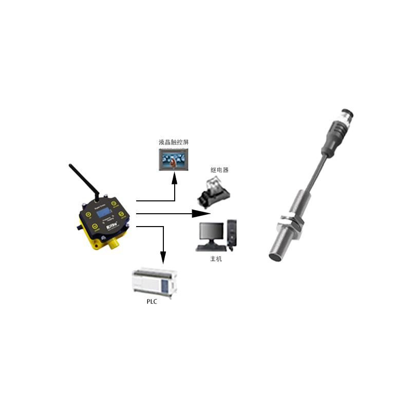
The vast majority of M30 3-wire sensors operate on the inductive principle. They generate a high-frequency oscillating electromagnetic field at their active face. When a metallic object (ferrous or non-ferrous, depending on the sensor type) enters this field, eddy currents are induced within the target. This causes a change in the oscillation amplitude within the sensor's internal circuit. This change is detected and processed, triggering a solid-state switching action in the output stage. Inductive sensors are ideal for detecting metals and are immune to common environmental factors like dust, oil, and non-metallic debris.
Decoding the 3-Wire Configuration
The "3-wire" system is the most common DC-powered configuration, prized for its simplicity. The three wires are:
1. Brown (or +V): This wire connects to the positive supply voltage (typically 10-30V DC).
2. Blue (or 0V): This wire connects to the negative supply voltage or ground (0V DC).
3. Black (or Signal Output): This is the switched output wire.
The output can be one of two types, defined by the internal switching element:
NPN (Sinking) Output: In this configuration, the black wire is connected to the load (e.g., a PLC input). When the sensor detects a target, it switches the black wire to connect to the 0V (Blue) line, sinking current from the load to ground. The load's other side must be connected to +V.
PNP (Sourcing) Output: Here, when activated, the sensor switches the black wire to connect to the +V (Brown) line, sourcing current to the load. The load's other side is then connected to 0V.
Choosing between NPN and PNP is critical and depends on the input circuitry of your controller (PLC, relay module). PNP is more common in European and many modern global designs, while NPN is often found in Asian-made equipment.
Key Specifications and Selection Criteria
When selecting an M30 3-wire proximity sensor, engineers must consider several parameters:
Sensing Distance (Sn): The rated operating distance. For a standard M30 inductive sensor, this is typically 10mm or 15mm. A factor of 0.8-0.9 is often applied for reliable real-world operation.
Output Type: As above, NPN (NO/NC) or PNP (NO/NC). NO (Normally Open) means the output is off with no target present; NC (Normally Closed) is the opposite.
Supply Voltage Range: Usually 10-30V DC, offering compatibility with common industrial 24V DC systems.
Switching Frequency: The maximum number of on/off cycles per second, important for high-speed counting or positioning applications.
Housing Material: Choose based on the environment (e.g., stainless steel for corrosive or washdown areas).
Protection Rating: IP67 and IP69K ratings are common, indicating protection against dust ingress and high-pressure water jets, respectively.
Target Material: Standard sensors work best on steel; reduced sensing distance applies for aluminum, brass, or copper. Special versions are available for non-ferrous metals.
Installation and Application Best Practices
Proper installation ensures optimal performance and longevity. Maintain the specified sensing distance from the target. Ensure lateral clearance between adjacent sensors to prevent mutual interference. Be mindful of the sensing field's shape and potential "blind zones" near the threaded barrel. These sensors are extensively used for position detection of machine parts, limit switching, rotary encoder synchronization, piece counting on conveyors