Proximity sensors are critical components in modern steering gear systems, providing precise detection of mechanical position without physical contact. These sensors enhance reliability, reduce wear, and improve safety in applications ranging from automotive steering to industrial automation. Understanding the schematic design of such sensors is essential for engineers aiming to optimize performance and integration.
The core principle of a proximity sensor in steering gear involves detecting the presence or absence of a target, typically a metal component like a gear tooth or actuator arm, using electromagnetic or capacitive methods. Inductive proximity sensors are most common due to their robustness in detecting ferrous metals. The schematic includes an oscillator circuit that generates a high-frequency electromagnetic field. When a metal target enters this field, eddy currents are induced, causing a change in the oscillator's amplitude. This change is detected by a threshold circuit, which triggers an output signal—often a digital switch or analog voltage—to indicate proximity.
A typical schematic diagram for an inductive proximity sensor consists of several key sections: the oscillator, demodulator, amplifier, and output stage. The oscillator, usually built around a coil and capacitor, operates at frequencies between 100 kHz and 1 MHz. The coil's inductance varies with the target distance, altering the oscillation. The demodulator converts this AC signal to DC, which is then amplified to drive the output. In steering gear applications, the output may connect to a microcontroller or PLC, enabling real-time feedback for position control. For example, in an electric power steering (EPS) system, the sensor monitors the steering column's rotation, ensuring accurate torque assistance.
Design considerations for these schematics focus on environmental factors like temperature fluctuations, vibration, and electromagnetic interference (EMI). Shielding and filtering components, such as ferrite beads and capacitors, are integrated into the schematic to minimize noise. Additionally, power supply stability is crucial; voltage regulators and protection diodes are included to prevent damage from surges or reverse polarity. The sensor's housing and mounting also influence performance, with schematics often specifying grounding points to reduce stray capacitance.
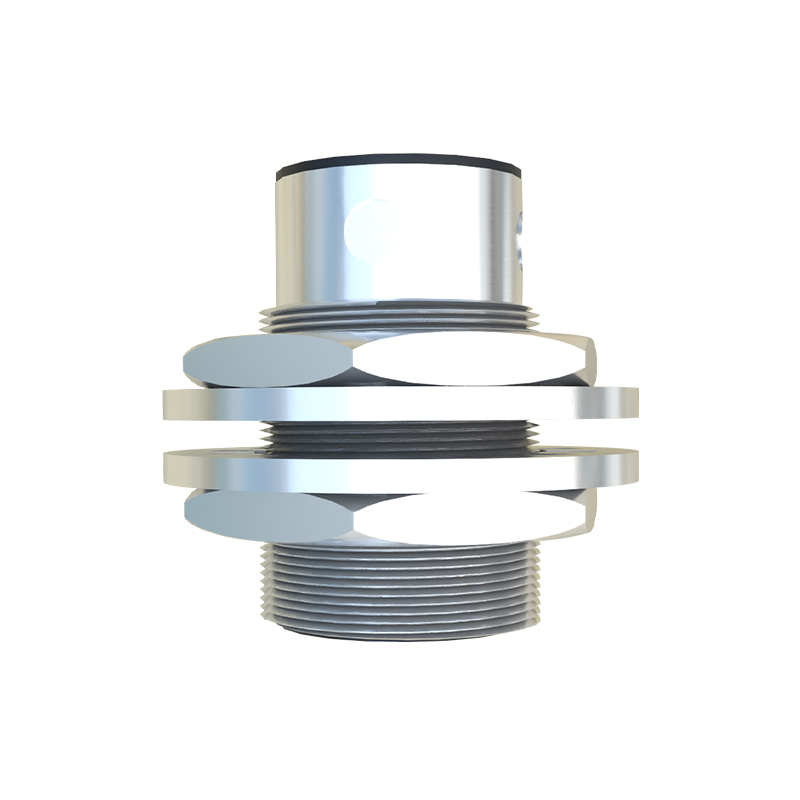
In practice, engineers must select components based on the steering gear's operational requirements. For instance, a sensor in an automotive steering system might use a 12V DC supply with a PNP output configuration, while industrial machinery could require 24V DC with NPN logic. The schematic should detail these specifications, along with connection diagrams for wiring to the steering control unit. Testing and calibration steps, such as adjusting the sensing range via potentiometers in the circuit, are also part of the design process to ensure repeatability and accuracy.
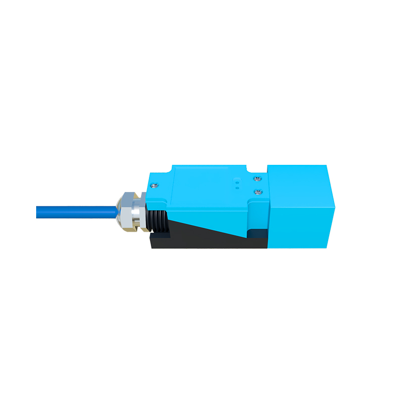
Advancements in proximity sensor technology have led to integrated ICs that simplify schematic design. Modern sensors may incorporate microprocessors for self-diagnostics and digital communication protocols like IO-Link, allowing for smarter steering systems. However, the fundamental schematic principles remain rooted in electromagnetic theory. By mastering these diagrams, engineers can troubleshoot issues, customize sensors for specific steering applications, and contribute to innovations in safety and efficiency. Ultimately, a well-designed proximity sensor schematic is pivotal for achieving seamless automation and responsive control in steering gear, driving progress across transportation and manufacturing sectors.