Proximity sensors are indispensable components in modern industrial automation, providing non-contact detection of metallic and, in some cases, non-metallic objects. Among various installation methods, flush mounting (or embeddable mounting) is a critical technique often required for specific operational environments and sensing needs. This guide delves into the principles, procedures, and best practices for the correct flush mounting of inductive proximity sensors, the most common type used for metal detection.
Understanding Flush Mounting
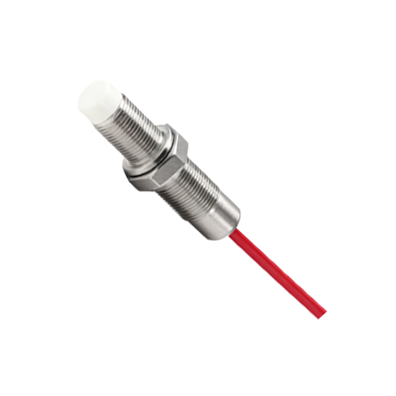
Flush mounting refers to installing a proximity sensor so that its sensing face is level with, or recessed within, the surface of the mounting bracket or machine structure. This is in contrast to non-flush mounting, where the sensor's head protrudes. The primary advantage of flush mounting is physical protection. The sensor is shielded from direct mechanical impact, abrasion, or shear forces, significantly extending its operational lifespan in harsh environments like material handling, machining, or mobile equipment.
However, this protection comes with a trade-off: a reduced sensing range. When flush-mounted, the sensor's electromagnetic field is partially constrained by the surrounding ferrous metal of the mounting structure. This typically cuts the nominal sensing distance (Sn) by 50% or more. For instance, an 18mm cylindrical sensor with a 10mm nominal range might only achieve 4-5mm when flush-mounted. It is imperative to consult the manufacturer's datasheet for the exact "usable sensing distance" under flush mount conditions.
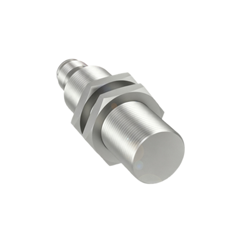
Key Installation Steps and Considerations
1. Mounting Hole Preparation: The mounting hole must be drilled and machined to the exact specifications in the sensor's datasheet. Tolerances are tight, typically within ±0.1mm. An oversized hole can allow the sensor to move, affecting repeatability, while an undersized hole can damage the sensor housing during installation. The hole must be deep enough to allow the sensing face to sit flush. Deburring the hole is essential to prevent damage to the sensor's O-ring or housing.
2. Material Considerations: Flush mounting is designed for installation into ferrous metal (e.g., mild steel). Mounting into non-ferrous materials like aluminum, stainless steel, or plastic does not provide the intended shielding effect and can unpredictably alter the sensing characteristics. Some sensors are specifically designed for "non-ferrous embeddable" applications; these must be selected explicitly.
3. Sensor Selection: Not all proximity sensors are suitable for flush mounting. Only sensors designated as "flush-mountable" or "embedddable" should be used. Their internal coil and shield design are optimized to allow the magnetic field to project forward despite the surrounding metal. Attempting to flush-mount a non-flush-mountable sensor will result in a severe, often non-functional, reduction in range.
4. Installation Procedure:
Clean the mounting hole and sensor housing.
If the sensor has an O-ring, ensure it is properly seated and lightly lubricated if recommended.
Carefully insert the sensor axially into the hole. Avoid angular insertion.
Secure the sensor using the prescribed method—usually a locknut on threaded-body sensors. Use a torque wrench to apply the correct tightening torque specified by the manufacturer. Over-tightening can crush the housing or distort threads.
For cylindrical sensors, the use of a standard wrench on the hex section is standard; never tighten by twisting the sensor body or cable.
5. Testing and Alignment: After installation, perform rigorous testing with the target material under real operating conditions. Verify the repeatability of switching at the required distance. Ensure that no other metal objects (like bolts, brackets, or moving machine parts) are within the sensor's lateral sensing zone, as they can cause false triggering. Maintain a minimum clearance around the sensor, as specified in the datasheet (often 1-2 times the sensor's diameter).
Troubleshooting Common Flush Mount Issues
Inconsistent Sensing/Chattering: Often caused by a loose sensor, an oversized mounting hole, or vibration. Re-tighten the locknut to the correct torque and check hole dimensions.
No Output: Verify the sensor is truly flush-mountable. Check for wiring errors (sourcing vs. sinking, PNP vs. NPN). Ensure the target is within the drastically reduced effective sensing range.
Reduced Range Beyond Specifications: Likely caused by mounting in thick non-ferrous metal or having excessive lateral metal too close to the sensing face. Review the installation environment against the sensor's installation guidelines.
Conclusion
Proper flush mounting is a precise engineering task that balances mechanical protection with sensing performance. Success hinges on selecting the correct sensor model