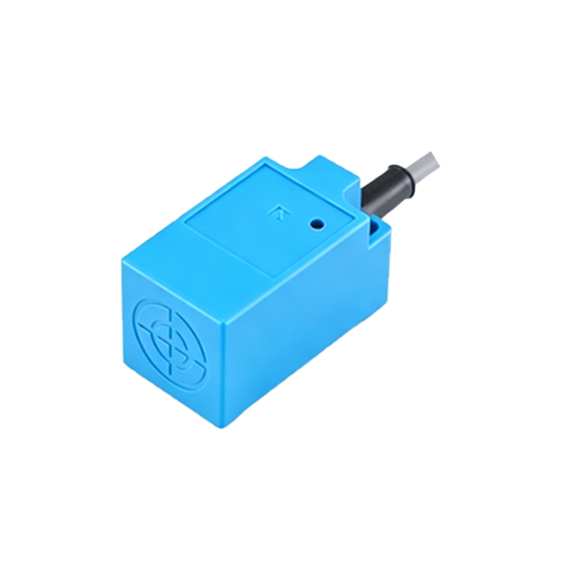
In the world of electronic design and schematic interpretation, understanding component symbols is fundamental. The proximity sensor, a device that detects the presence or absence of an object without physical contact, has a distinct and standardized representation in circuit diagrams. Unlike basic components such as resistors or capacitors, its symbol conveys both its function and its operational principle.
The most common and generic symbol for a proximity sensor resembles a simple rectangular box or a diamond shape with two diagonal lines inside, representing the sensing field. Two connection lines, denoting the power supply (typically labeled Vcc and GND), extend from the body. The key feature is the output line, which may be shown with a switch-like symbol (either normally open (NO) or normally closed (NC)) to indicate its digital switching behavior. Often, a wavy line or a set of concentric arcs emanates from the front of the symbol, graphically depicting the emitted sensing beam or field—whether it is infrared, ultrasonic, capacitive, or inductive. For inductive proximity sensors (common for metal detection), the symbol might include a coil representation inside the box. For capacitive sensors, the symbol sometimes incorporates two parallel plates.
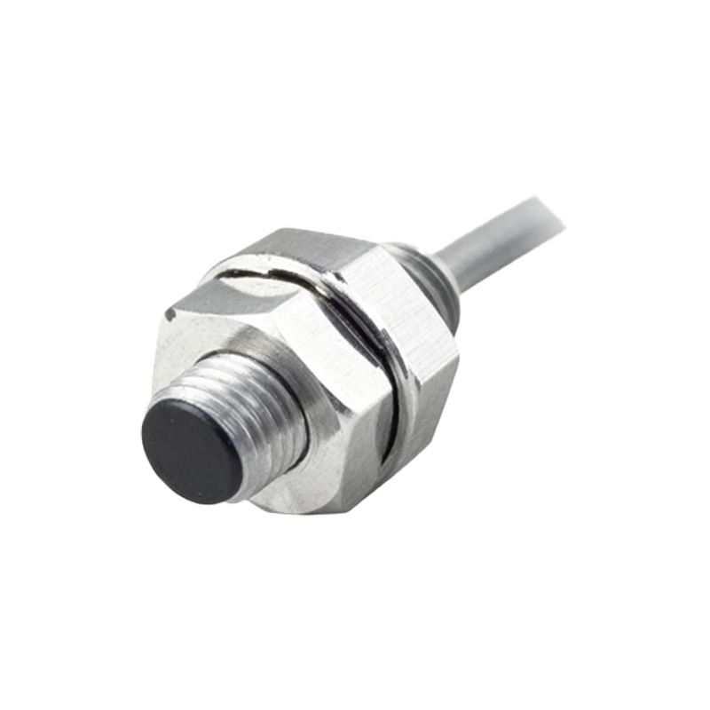
It is crucial to note that while a core symbol exists, variations are common. Different manufacturers or specific international standards (like IEC or ANSI) may present slight graphical modifications. Therefore, always cross-reference the symbol with the specific part's datasheet. The symbol never operates in isolation; it is part of a larger circuit. Typically, the sensor's output is connected to a load, such as a relay coil, a PLC input, or an LED indicator. A pull-up or pull-down resistor is frequently integrated at the output to ensure a defined logic state.
Understanding this symbol allows engineers and technicians to quickly identify the sensor's role in a system—be it for object counting, position verification, or safety interlocks. It communicates that the circuit will react based on a non-contact detection event. When analyzing a schematic, look for this symbol to pinpoint where the physical world (object presence) interfaces with the control logic of the electronic circuit. Mastery of this and other component symbols is the first step in proficient circuit design, troubleshooting, and system integration, forming the essential language of electronics.