In the realm of industrial automation and control systems, proximity sensors are indispensable components for detecting the presence or absence of an object without physical contact. Their reliability and performance, however, are fundamentally dependent on one critical aspect: proper wiring. Incorrect or substandard wiring can lead to sensor malfunction, erratic system behavior, and costly downtime. This guide delves into the essential principles and best practices for proximity sensor connection wiring, tailored for electrical engineers and technicians.
Proximity sensors primarily fall into two categories based on their output configuration: 2-wire, 3-wire, and occasionally 4-wire designs. Understanding the distinction is the first step to correct installation.
2-Wire Proximity Sensors: These function similarly to a switch in series with the power supply and the load. They are simpler to install as they require only two connection points, typically labeled Brown (or +) and Blue (or -). A key consideration is the voltage drop across the sensor, which must be accounted for when sizing the load. They are polarity-sensitive in DC versions, meaning incorrect connection will prevent operation.
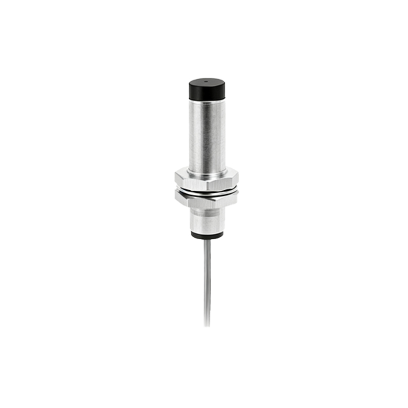
3-Wire Proximity Sensors: The most common type in modern installations, they offer separate paths for power supply and load switching, leading to more stable performance. They feature three wires:
Brown (or +V): Connected to the positive DC supply voltage or the hot line in AC.
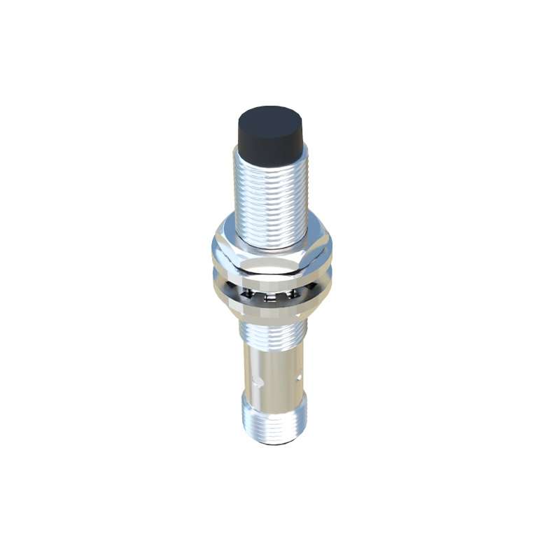
Blue (or 0V/Common): Connected to the negative DC supply or neutral (AC).
Black (or Output): The switched output signal. This can be either NPN (sinking) or PNP (sourcing) for DC sensors, a crucial distinction.
NPN vs. PNP Outputs: This is a cornerstone concept in sensor wiring. An NPN sensor switches the negative (0V) line to the load; the load is connected between the positive supply and the sensor's black wire. Conversely, a PNP sensor switches the positive voltage line to the load. Mismatching the sensor output type with the controller input (e.g., connecting a PNP sensor to a sinking input) is a common wiring error that results in failure.
Wiring Best Practices and Critical Considerations:
1. Power Supply & Voltage Ratings: Always verify the sensor's operating voltage range (e.g., 10-30V DC, 90-250V AC) and ensure your supply matches. Use a regulated, stable power supply to avoid voltage spikes that can damage the sensor's internal electronics.
2. Wire Selection and Glanding: Use shielded, multi-strand copper cables of appropriate gauge for the current rating. The shield must be grounded at the control panel end only to prevent ground loops and mitigate electromagnetic interference (EMI) from nearby motors or frequency drives. Proper cable glands ensure IP (Ingress Protection) ratings are maintained.
3. Load Considerations: Do not exceed the sensor's maximum switching current. For inductive loads (like relays, solenoids), use a protective circuit such as a flyback diode (for DC) or a snubber network (for AC) across the load to suppress voltage transients that can erode or destroy the sensor's output transistor.
4. Wiring Diagrams and Documentation: Never proceed without consulting the manufacturer's datasheet. The color code and function of wires can vary, especially between different global manufacturers. Adhere strictly to the provided schematic.
5. Installation Environment: Maintain proper separation between sensor cables and high-power AC lines. Route them in separate conduits or trays whenever possible. For long cable runs, consider voltage drop and potential signal degradation.
6. Testing and Commissioning: After wiring, perform a systematic check. Verify power at the sensor terminals, then test the output signal with the target object present and absent, using a multimeter or the PLC's input status indicators.
Troubleshooting Common Wiring Issues:
Sensor Not Powering On: Check polarity for DC sensors, verify fuse integrity, and confirm supply voltage.
Erratic or No Output Signal: Inspect for loose connections, damaged cable shielding, or EMI sources. Verify the load current is within limits and check for a short circuit.
Sensor Stays On: This could indicate a wiring error where the load is incorrectly connected, or in rare cases, sensor failure due to overload.
In conclusion, the integrity of a proximity sensor's signal chain is only as strong as its wiring. A methodical approach—starting with correct sensor type identification (NPN/PNP, 2/3-wire), adhering to manufacturer diagrams, employing proper cabling and shielding techniques, and accounting for the load characteristics—is non-negotiable for robust system performance. By mastering these wiring fundamentals