Proximity sensors integrated into door handles have become a standard feature in modern automated access systems, industrial machinery, and automotive applications. These non-contact sensors, often inductive or capacitive types, detect the presence of a hand or object to trigger an action such as unlocking a door or starting a process. A common and critical failure mode in these systems is an open circuit, or断路, within the sensor or its associated wiring. This failure renders the system inoperative, posing significant safety, security, and operational challenges. Understanding the root causes, diagnostic procedures, and effective solutions is paramount for maintenance engineers and system designers.
The primary function of a door handle proximity sensor is to provide a reliable signal to a control unit. An inductive sensor generates an electromagnetic field; when a conductive target (like a hand) enters this field, it causes a change in the oscillation amplitude, which the sensor's circuitry detects and converts into a switching signal. A capacitive sensor works on the principle of detecting changes in capacitance caused by the proximity of any object, conductive or not. An open circuit failure interrupts the signal path entirely. This can occur at several points: within the sensor coil or internal electronics, at the wire terminations (especially in the flex area where the handle is repeatedly manipulated), at the connector interfaces, or in the cable run itself due to pinch points, vibration, or corrosion.
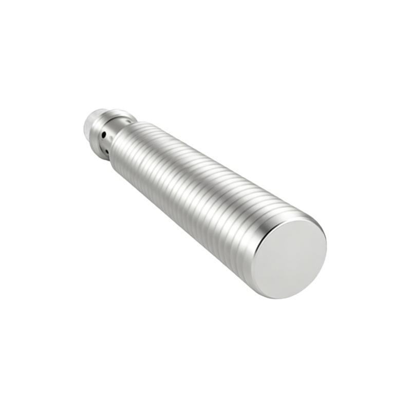
Diagnosing an open circuit requires a systematic approach. The first step is to verify the symptoms. The system may fail to activate upon touch, or the control panel may display a specific fault code indicating "sensor open" or "loss of signal." Initial checks should always include confirming power supply voltage at the sensor connector as per datasheet specifications (commonly 10-30V DC for industrial sensors). Using a digital multimeter (DMM) set to resistance or continuity mode is the next step. With the sensor disconnected from power and the controller, measure the resistance across the sensor's output wires (typically the brown/blue wires for power and black/white for signal in a 3-wire DC sensor). An inductive proximity sensor typically shows a finite coil resistance (e.g., 50-2000 ohms, depending on type). A reading of "OL" or infinite resistance confirms an open circuit.
Further isolation is necessary. If the initial reading is open, test the sensor alone by disconnecting it from its cable harness, if possible. Measure directly across its terminals. If the sensor itself shows continuity, the fault lies in the cabling or connectors. Perform a continuity check on each wire in the cable from the sensor end to the control cabinet end, ensuring each conductor is not broken and is isolated from others. Vibration and repeated mechanical stress are the most common culprits for wire fatigue and breakage, particularly where the cable enters the door handle assembly. Environmental factors like moisture ingress can lead to corrosion on connector pins or PCB traces inside the sensor housing, creating a high-resistance or open connection.
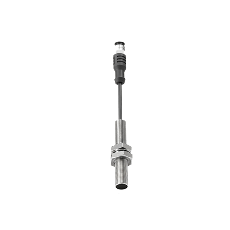
Beyond simple wire breaks, other causes can manifest as an open circuit. A failed oscillator or amplifier component within the sensor's encapsulated electronics can create an internal open. Excessive supply voltage (transients or surges) can damage internal semiconductors. In capacitive sensors, contamination (dirt, grease, ice) building up on the active face can sometimes cause a functional failure that mimics an open circuit, though this is usually a sensing range issue rather than a true electrical open.
Solutions and preventive measures are equally critical. For a confirmed broken wire, the repair involves replacing the damaged cable section or the entire harness, ensuring strain relief is properly installed at the handle entry point. Use cables with high flex-cycle ratings for dynamic applications. For a failed sensor unit, replacement is the only option; these are typically sealed units not intended for repair. When installing new sensors, adhere strictly to mounting specifications regarding flush or non-flush mounting distances and ensure the sensing face is clean and unobstructed.
From a design perspective, implementing diagnostic features in the control system can preempt failures. Some modern sensors and PLC input modules offer built-in diagnostics that monitor current draw or signal integrity, providing early warnings. Using connectors with IP67 or higher ratings in harsh environments prevents moisture-related corrosion. Redundant sensor configurations or periodic functional testing as part of preventive maintenance schedules can significantly reduce unexpected downtime.
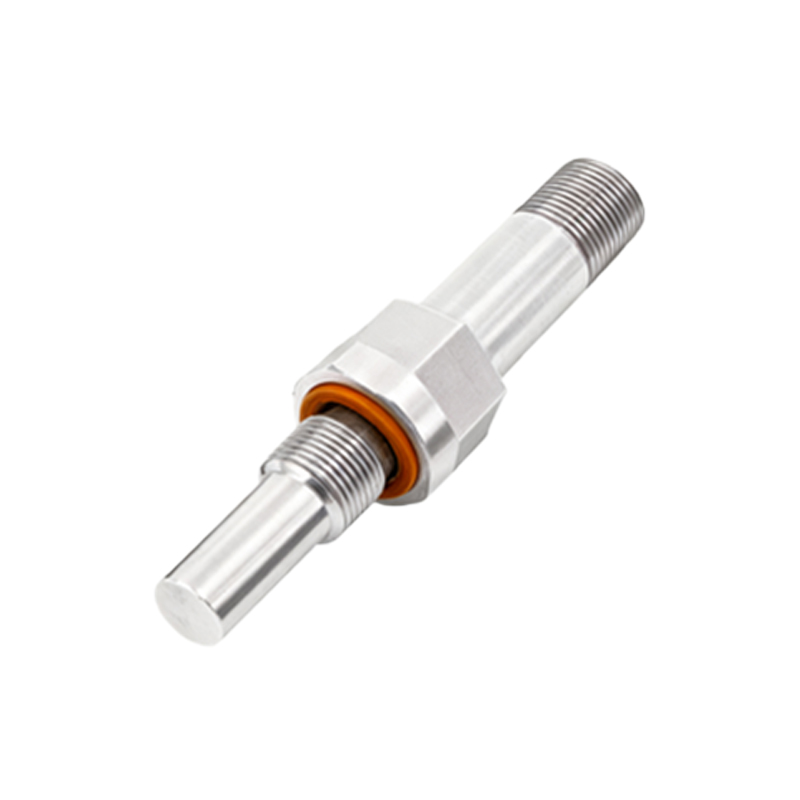
In conclusion, an open circuit in a door handle proximity sensor is a definitive failure that halts operation. Successful resolution hinges on a logical diagnostic sequence: symptom verification, power check, resistance measurement, and systematic isolation of the fault to the sensor, cable, or connector. By understanding the common failure mechanisms—primarily mechanical wire fatigue and environmental damage—engineers can not only fix existing problems but also design and install more robust systems. Prioritizing high-quality components, proper installation with adequate strain relief, and environmental protection will maximize the mean time between failures (