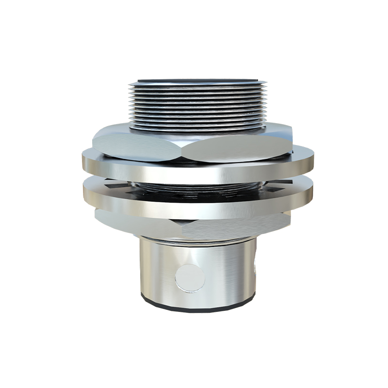
In industrial automation, proximity sensors play a critical role in detecting the presence or absence of objects without physical contact. These sensors, including inductive, capacitive, and photoelectric types, are widely used for positioning, counting, and safety applications. Integrating a proximity sensor module with a Programmable Logic Controller (PLC) is a fundamental task for engineers and technicians. This guide provides a step-by-step approach to wiring, configuring, and programming proximity sensors with PLCs, ensuring reliable operation in diverse industrial environments.
First, understand the sensor specifications. Proximity sensors typically output a digital signal, either PNP (sourcing) or NPN (sinking), which must match the PLC input type. Check the sensor's operating voltage (commonly 12-24V DC), sensing range, and output current. For wiring, connect the sensor's power supply lines to a suitable DC source. The output wire is linked to a PLC digital input terminal. Always refer to the sensor and PLC manuals for pin diagrams. For instance, with a 24V DC PNP sensor, connect the brown wire to +24V, the blue wire to 0V, and the black output wire to the PLC input. Ensure proper grounding and use shielded cables in electrically noisy environments to prevent false triggers.
Next, configure the PLC hardware. Most modern PLCs, such as Siemens S7-1200 or Allen-Bradley CompactLogix, allow easy setup via software like TIA Portal or Studio 5000. Assign the connected input terminal to a memory address (e.g., I0.0 for input 0). Verify the input module's voltage rating matches the sensor output. Some PLCs require setting the input filter time to debounce signals, especially for fast-moving objects. Adjust parameters like response time to suit the application speed—typically, proximity sensors have response times under 1 ms, but PLC scan cycles may affect overall performance.
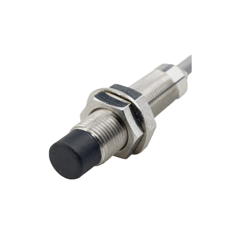
Programming the PLC involves ladder logic or structured text. Create a simple rung to read the sensor status. For example, in ladder logic, use a normally open contact addressed to the sensor input (e.g., I0.0) to control an output coil (e.g., Q0.0) for an actuator. Add logic for counting: use a counter instruction triggered by the sensor's rising edge to increment counts for production monitoring. Implement safety interlocks by combining sensor inputs with emergency stop circuits. For analog proximity sensors providing distance data, scale the input values in the PLC program to obtain precise measurements.
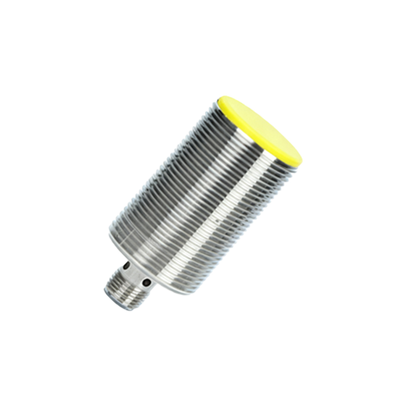
Testing and troubleshooting are essential. Simulate the program in offline mode to check logic, then deploy it to the PLC. Monitor the input status LEDs on the PLC and sensor to confirm activation. Common issues include wiring errors (e.g., reversed polarity), insufficient sensing range, or electrical interference. Use a multimeter to verify voltage levels. If the sensor fails to trigger, adjust its position or sensitivity potentiometer. Regularly maintain sensors by cleaning detection surfaces and checking cable integrity.
In summary, interfacing proximity sensor modules with PLCs requires attention to electrical compatibility, precise wiring, and logical programming. By following these practices, engineers can enhance system reliability and efficiency in automation projects.