In the realm of industrial automation and control systems, proximity switches are fundamental components for non-contact detection. Among these, the Normally Closed (NC) proximity switch holds a specific and critical role. This article delves into the operational principle of normally closed inductive proximity switches, a common type, explaining their function, typical circuitry, and key application considerations.
At its core, a proximity switch is a sensor that detects the presence or absence of a target object without physical contact. It does so by emitting an electromagnetic field, light beam, or ultrasonic waves. The "normally closed" designation refers to the state of its output switching element (like a solid-state switch or relay contacts) when the sensor is in its idle or non-activated condition. For an NC sensor, the output circuit is closed (allowing current to flow) when no target is within its sensing range. When a target enters the detection zone, the sensor activates and opens the output circuit, interrupting the current flow. This behavior is the inverse of a Normally Open (NO) sensor.
Focusing on the widely used inductive proximity switch, its operation is based on the principle of electromagnetic induction. The key internal components include an oscillator coil, a detection circuit, a trigger circuit, and an output switching device. In its resting state (no metal target present), the high-frequency oscillator generates an alternating electromagnetic field at the sensing face. The energy loss in this oscillating circuit is minimal, and the detection circuit maintains a steady state. In this condition, the output transistor (acting as the switch) is in a conducting state for an NC configuration. This means the signal line (often the black wire in a 3-wire DC sensor) is internally connected to the negative voltage line, completing the circuit for the connected load, such as a PLC input or a relay coil.
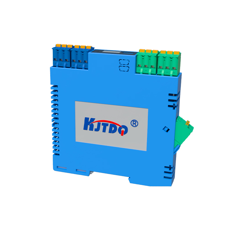
When a ferrous or non-ferrous metal target approaches the active sensing face within the specified nominal sensing distance (Sn), it enters the oscillating electromagnetic field. The target induces eddy currents on its surface, which draw energy from the oscillator. This increased energy dampening causes the amplitude of the oscillation to decrease. The detection circuit monitors this amplitude. Once the amplitude drop reaches a predefined threshold, the trigger circuit is activated. This trigger circuit then commands the output switching transistor to turn off (cease conduction). Consequently, the internal connection between the signal line and the negative supply is broken—the switch "opens." The load circuit is now interrupted, signaling the controller that a target has been detected.
The wiring configuration is crucial for proper operation. A standard 3-wire DC sensor has brown (positive), blue (negative/0V), and black (signal output) wires. For an NC sensor, in the absence of a target, there is voltage present at the black wire (approximately 0V relative to negative, meaning it is "sinking" current). When a target is detected, the black wire switches to a high-impedance state, effectively becoming open circuit. It is vital to consult the datasheet, as some PNP (sourcing) sensors can also be configured in an NC mode, where the logic is inverted regarding voltage presence.
The choice between Normally Closed and Normally Open configurations is driven by safety and control logic requirements. NC sensors are often employed in safety-critical or monitoring applications where a wire break or loss of power should cause an alarm or safe shutdown. This is because a broken wire in series with an NC sensor mimics the "target present" state (open circuit), providing a fail-safe indication. For instance, a guard door monitored by an NC sensor will trigger a stop if the door is opened (target moves away, circuit opens) OR if the sensor's wiring is cut. In standard process automation, the choice depends on whether the control logic requires an active-high or active-low signal upon detection.
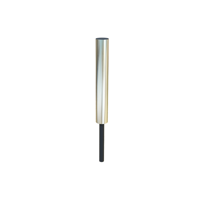
Key parameters to consider when selecting and applying an NC proximity switch include the sensing distance, hysteresis (the difference between the switch-on and switch-off points to prevent chatter), response frequency, output current rating, and environmental factors like temperature and material compatibility. Proper mounting, ensuring a stable power supply, and maintaining adequate clearance from other metal objects are essential for reliable operation.
In summary, the normally closed proximity switch operates on a "closed until detected" principle. Its output provides a continuous signal path under normal conditions and interrupts that path upon target detection. Understanding this fundamental behavior, alongside its wiring and the rationale for its use, is essential for designing robust, safe, and efficient automated control systems across manufacturing, packaging, material handling, and countless other industrial sectors.