Calibrating a laser sensor is a critical procedure to ensure accurate measurements, reliable operation, and longevity in industrial environments. This guide outlines a systematic approach, adhering to industry best practices, for technicians and engineers.
The calibration process begins with thorough preparation. First, consult the sensor's specific technical datasheet and user manual from the manufacturer. These documents provide essential parameters such as measurement range, output signal type (e.g., analog 4-20mA, digital IO-Link, Ethernet/IP), and recommended environmental conditions. Ensure the sensor is powered down before any physical adjustments. Clean the sensor's lens meticulously with a soft, lint-free cloth and an appropriate optical cleaner to remove dust, oil, or debris that could scatter the laser beam and cause measurement drift. Verify that the mounting is secure and stable, as vibration can introduce significant error.
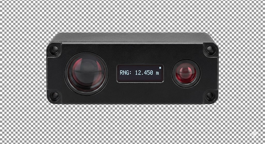
Next, establish a known reference target. This is the cornerstone of accurate calibration. Use a calibration standard with a highly reflective, flat surface, such as a certified gauge block or a dedicated calibration plate provided by the sensor manufacturer. The target material and surface finish should match, as closely as possible, the actual application's target material. Position this reference target at a precisely known distance within the sensor's specified measuring range. For distance-measuring sensors, this might be the minimum, midpoint, and maximum distances. For presence detection, use targets that definitively represent the "object present" and "object absent" states.
Power on the sensor and connect it to your monitoring system, which could be a PLC (Programmable Logic Controller), a dedicated display unit, or software provided by the manufacturer. Most modern laser sensors feature a teach-in or auto-calibration function. This automated process typically involves pressing a button or sending a command to store the output values for the "near" and "far" reference points you have established. The sensor's internal processor then calculates a linearization curve. Always follow the exact sequence prescribed in the manual for this function.
For sensors requiring manual adjustment, you will work with potentiometers or navigate a digital menu. The key parameters are typically the zero point (offset) and the span (gain). With the reference target at the minimum distance, adjust the zero or offset control until the output signal reads the correct value (e.g., 4mA or 0V). Then, move the target to the maximum distance and adjust the span or gain control to achieve the correct maximum output (e.g., 20mA or 10V). You may need to iterate between these two points several times, as adjusting one can affect the other. For digital sensors, these adjustments are made via software, where you input the actual measured distance and the sensor calculates the correction internally.
After the initial calibration, perform a validation check. Move the reference target to several intermediate points across the entire measurement range and record the sensor's output. Compare these readings against the known values. The error should fall within the sensor's stated repeatability and linearity specifications from the datasheet. Document all calibration data, including date, technician, reference values, sensor settings, and final validation results. This creates a traceable history for quality assurance and predictive maintenance.
Environmental factors are a major source of post-calibration drift. Temperature fluctuations can affect both the sensor's electronics and the wavelength of the laser diode. If the sensor will operate in a variable temperature environment, it is advisable to perform calibration at the average operational temperature or use a sensor with built-in temperature compensation. Ambient light, especially from other lasers or strong incandescent sources, can interfere with the receiver. Ensure the installation site minimizes such interference, or use sensors with modulated laser light and synchronous detection to reject ambient noise. Finally, the target surface properties—color, reflectivity, texture, and material—directly impact the amount of light returned to the receiver. A sensor calibrated on a bright white surface may under-read on a dark, matte black surface. For applications with varying surface properties, choose a sensor with background suppression or true background suppression technology, and calibrate using a target that represents the worst-case (e.g., least reflective) surface.
Routine verification is essential. Establish a preventive maintenance schedule to check calibration weekly, monthly, or quarterly, depending on the criticality of the application and the operational harshness. Sudden deviations often indicate a problem such as a dirty lens, loose connection, or impending component failure. By following this disciplined approach to calibration, validation, and environmental consideration, you ensure that your laser sensor delivers the precision and reliability demanded by modern automation, quality control, and safety systems.