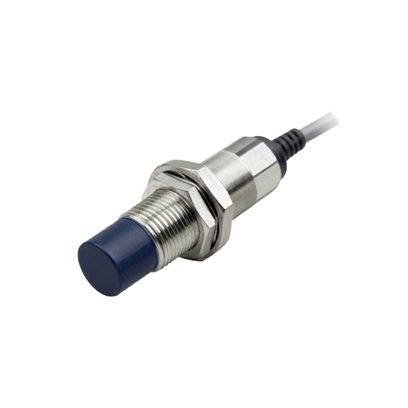
In the realm of industrial automation and control systems, proximity sensors are indispensable components for non-contact detection of objects. Their reliability and precision hinge not only on selecting the correct sensor type but also on proper installation, with wiring being a fundamental aspect. For electrical engineers and technicians, understanding the two primary wiring methods for proximity sensors—2-wire and 3-wire configurations—is crucial for ensuring optimal performance, safety, and system integration. This guide delves into the characteristics, applications, and key considerations for each method, presented in a manner consistent with standard industry practices and English technical documentation.
The 2-wire proximity sensor represents the simplest wiring scheme. As the name implies, this sensor requires only two wires for its operation: one for power supply (typically labeled L+ or Brown) and the other for both the load and the return path (often labeled L- or Blue). In this configuration, the sensor and the load (such as a PLC input, relay, or indicator lamp) are connected in series. The sensor itself acts as a switch within the current path. When no target is detected, the sensor presents a high impedance (leakage current), allowing only a minimal "off-state" current to flow, insufficient to activate the load. Upon detecting a target, the sensor switches to a low-impedance state, allowing the full operating current to pass through and energize the load.
The primary advantage of the 2-wire system is its simplicity and direct replacement capability for mechanical limit switches, requiring no additional wiring for a separate power source for the sensor. It simplifies cabinet design and reduces initial wiring costs. However, engineers must pay close attention to the sensor's leakage current in the off-state. If this current is too high, it may inadvertently activate highly sensitive loads. Conversely, the voltage drop across the sensor when in the "on" state must be considered to ensure sufficient voltage reaches the load. This method is commonly used in applications where simplicity is paramount and load sensitivity is compatible with the sensor's electrical characteristics.
In contrast, the 3-wire proximity sensor is the most prevalent configuration in modern industrial control panels. This design features three distinct wires: a power supply positive (typically Brown), a power supply negative or common (Blue), and a separate output signal wire (Black, White, or another color depending on the output type). This architecture separates the sensor's internal circuitry power supply from the switched output signal path. The sensor is powered continuously between the Brown and Blue wires. The output wire provides a switched voltage or current signal relative to the common (Blue) wire, which then connects to the load.

The 3-wire sensors are further categorized by their output transistor type: NPN (sinking) and PNP (sourcing). An NPN sensor switches the negative side (common) to the load; when active, it connects the output to the negative supply, effectively "sinking" current. A PNP sensor switches the positive side; when active, it connects the output to the positive supply, "sourcing" current. The choice between NPN and PNP is critical and depends on the control system's input card configuration (sinking or sourcing input). The key benefits of the 3-wire system include negligible leakage current, minimal voltage drop in the signal path, faster switching speeds, and the ability to handle a wider range of load currents. It offers superior electrical performance and compatibility with programmable logic controllers (PLCs) and other solid-state control devices.
When selecting the appropriate wiring method, engineers must evaluate several factors. First, consider the existing control system architecture and the input specifications of the controller (PLC/DCS). Second, assess the available power supply and the need for electrical noise immunity; 3-wire sensors often provide better performance in electrically noisy environments. Third, factor in installation and maintenance logistics; 2-wire sensors offer simpler replacement, while 3-wire systems provide clearer diagnostic points (separate power and signal). Always consult the manufacturer's datasheet for specific wiring diagrams, voltage ranges, current ratings, and output types. Proper shielding and grounding, especially for DC sensors, are essential to prevent electromagnetic interference. Furthermore, for AC-powered 2-wire sensors, attention must be paid to inrush currents and the correct connection of live and neutral wires.
In summary, the dichotomy between 2-wire and 3-wire proximity sensor wiring is a fundamental decision point in control system design. The 2-wire method offers simplicity and direct compatibility with legacy switch replacements, while the 3-wire method provides enhanced performance, flexibility, and precision for sophisticated automation systems. A thorough understanding of their operational principles, advantages, and limitations empowers electrical professionals to design robust, efficient, and reliable sensing solutions tailored to the specific demands of any industrial application.