Proximity sensors are fundamental components in modern automation, robotics, and safety systems. Their ability to detect the presence or absence of an object without physical contact makes them indispensable. At the heart of every reliable sensor lies a well-designed schematic. This guide delves into the core principles, common circuit configurations, and critical considerations for creating effective proximity sensor schematics.
Understanding the basic operating principle is the first step. Most proximity sensors work by emitting a field or beam of electromagnetic radiation (like infrared light or an electromagnetic field) and then looking for changes in the return signal or field. The schematic must accurately translate this principle into electronic components. The two most prevalent types are inductive sensors (for metals) and capacitive sensors (for both metals and non-metals). Photoelectric sensors, using light beams, form another major category.
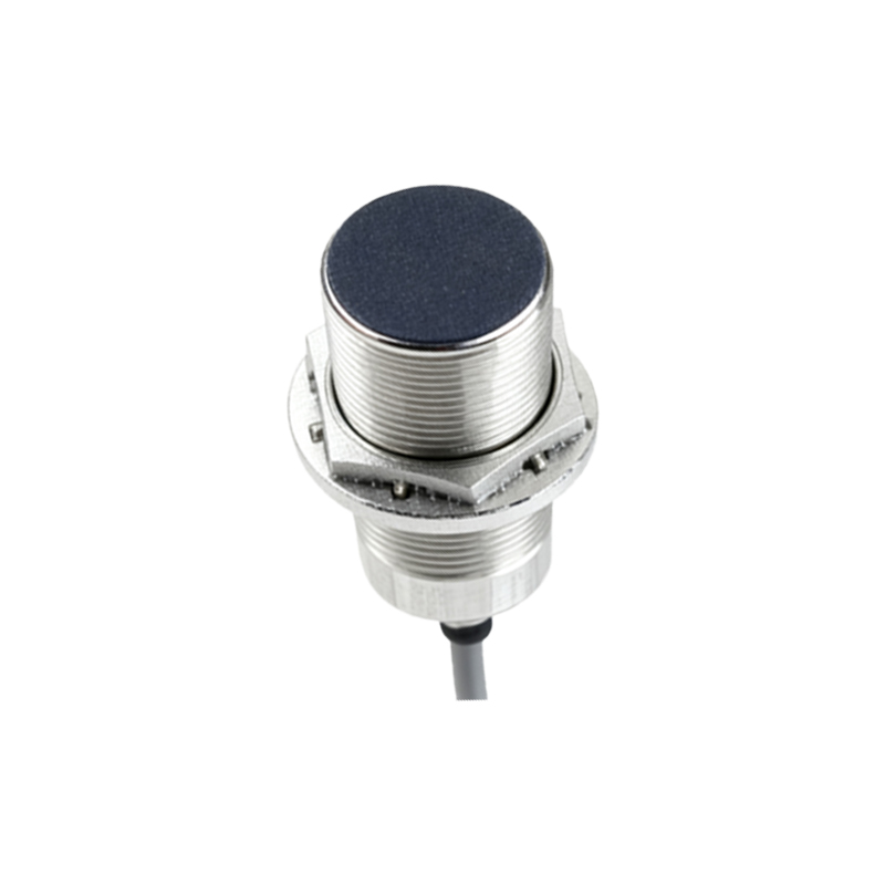
A typical inductive proximity sensor schematic revolves around an oscillator circuit. The core component is a coil (inductor) that generates a high-frequency oscillating electromagnetic field. When a metallic object enters this field, eddy currents are induced in the object, which loads the oscillator and causes a change in its amplitude or frequency. This change is detected by a subsequent threshold detection circuit (often a comparator), which then switches the state of the output stage. The output stage is crucial and is commonly configured as an NPN (sinking) or PNP (sourcing) transistor. The schematic must clearly define the load connection to the output (e.g., connected to positive voltage for NPN, or to ground for PNP) and include necessary protection components like flyback diodes for inductive loads or series resistors for LED indicators.
Capacitive sensor schematics are similar in structure but operate on a different principle. The sensing element forms one plate of a capacitor, with the target object (or the environment) acting as the other plate. The schematic includes an oscillator whose frequency is determined by this variable capacitance. As an object approaches, the capacitance increases, altering the oscillator's characteristics. This change is processed to trigger the output. These schematics often feature a sensitivity adjustment potentiometer, allowing calibration for different materials and distances.
Beyond the core detection circuit, a robust schematic incorporates several essential elements. Power supply conditioning is paramount. This includes decoupling capacitors placed close to the integrated circuits to filter noise and ensure stable operation. Voltage regulation may be necessary if the sensor operates from a wide input range. Protection against reverse polarity, overvoltage, and transient voltage spikes (using diodes, TVS diodes, or varistors) is critical for industrial durability, and these components must be clearly specified on the drawing.
Furthermore, the output interface requires careful design. For digital outputs, the choice between a relay, transistor, or open-collector configuration must suit the load. Analog output schematics, which provide a voltage or current proportional to distance, will include signal conditioning stages like amplifiers and filters. Status indication, usually via an LED with a current-limiting resistor, is a standard feature and must be included in the schematic with its connection path.
When interpreting or creating a proximity sensor schematic, pay close attention to the component ratings, signal flow, and grounding scheme. A proper grounding strategy, separating noisy digital grounds from sensitive analog signal grounds, is often the difference between a functional prototype and a reliable product. The physical layout, hinted at in the schematic by component placement notes, is equally important to prevent crosstalk and ensure the sensor's specified sensing range.
In conclusion, a proximity sensor schematic is more than just a collection of symbols; it is a blueprint for reliability and performance. A successful design balances the core sensing technology with robust power management, output driving capability, and comprehensive protection. Whether you are selecting a sensor for an application or designing a custom solution, a deep understanding of these schematic principles empowers you to make informed decisions and achieve optimal results in any detection task.