Radar proximity sensors are widely used in industrial automation, security systems, and smart devices for non-contact detection of objects. Understanding their working principle is essential for engineers and technicians in the electrical and automation fields. This article provides a detailed explanation of the radar proximity sensor principle with diagrams to illustrate key concepts.
Radar proximity sensors operate based on the principle of electromagnetic wave reflection. They emit high-frequency radio waves, typically in the microwave or millimeter-wave range, toward a target area. When these waves encounter an object, they reflect back to the sensor. The sensor's receiver detects the reflected waves and analyzes changes in frequency, phase, or time delay to determine the presence, distance, speed, or direction of the object.
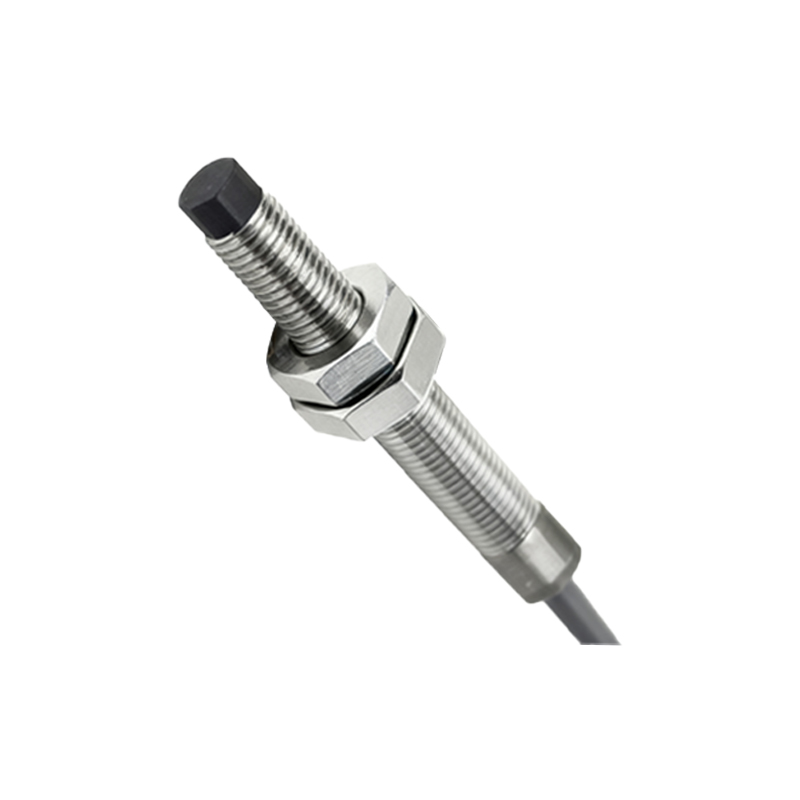
The core components of a radar proximity sensor include a transmitter, antenna, receiver, and signal processing unit. The transmitter generates electromagnetic waves using an oscillator, such as a voltage-controlled oscillator (VCO), which produces signals in frequencies like 24 GHz or 77 GHz, depending on the application. The antenna, often a patch or horn antenna, directs these waves toward the target. Modern sensors use integrated antennas for compact design.
Upon reflection, the waves return to the antenna, which couples them to the receiver. The receiver mixes the transmitted and reflected signals to produce an intermediate frequency (IF) signal. This mixing process, known as heterodyning, allows the sensor to extract information about the target. For instance, in a frequency-modulated continuous-wave (FMCW) radar sensor, the frequency of the transmitted signal varies linearly over time. The difference between the transmitted and reflected frequencies, called the beat frequency, is proportional to the distance to the object. The formula for distance calculation is: Distance = (c Δt) / 2, where c is the speed of light and Δt is the time delay. Alternatively, using frequency difference: Distance = (c T Δf) / (2 B), where T is the modulation period, Δf is the frequency difference, and B is the bandwidth.
Signal processing plays a crucial role in filtering noise and interpreting data. Microcontrollers or digital signal processors (DSPs) analyze the IF signal to compute parameters like range, velocity, and angle. Advanced sensors employ algorithms for motion detection or object classification. For example, Doppler radar sensors measure velocity by detecting frequency shifts due to motion, using the Doppler effect principle: Δf = (2 v f0) / c, where v is the target velocity and f0 is the transmitted frequency.
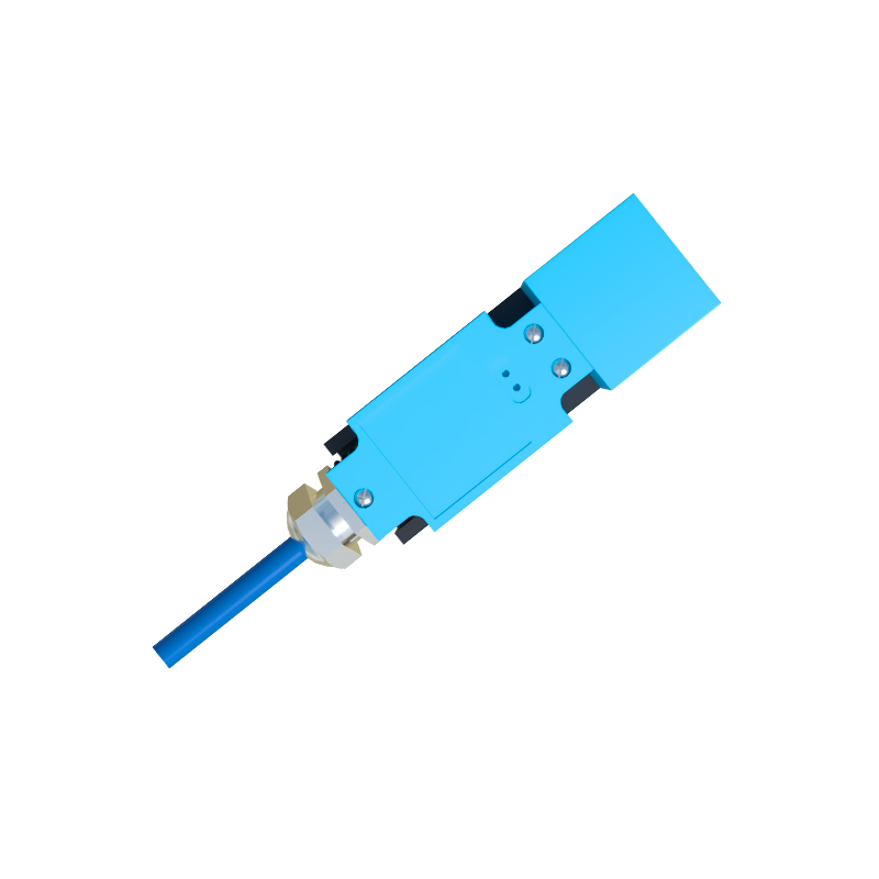
In terms of diagrams, a typical radar proximity sensor block diagram illustrates the flow from signal generation to output. It shows the transmitter module connected to the antenna, the receiver module with a mixer and amplifier, and the processing unit generating a digital or analog output. Another diagram depicts wave propagation: transmitted waves travel outward, hit an object, and reflect back, with arrows indicating direction and potential multipath effects. A timing diagram for FMCW radar displays frequency versus time, highlighting the transmitted chirp and reflected signal, with the beat frequency marked for distance calculation.
Applications of radar proximity sensors vary from factory automation, where they detect objects on conveyor belts, to automotive systems like blind-spot monitoring. They offer advantages over ultrasonic or infrared sensors, such as better performance in adverse conditions (e.g., dust, fog) and higher accuracy for moving targets. However, challenges include interference from other radar sources and limitations in detecting very small or absorbent materials.
To summarize, radar proximity sensors rely on electromagnetic wave reflection and signal analysis for precise detection. Diagrams help visualize components like antennas and wave interactions, while formulas explain distance and velocity computations. As technology advances, these sensors are becoming more integrated and efficient, driving innovation in IoT and Industry 4.0. Engineers should consider factors like frequency selection and environmental conditions when designing systems. For further details, refer to technical datasheets or industry standards like IEC 60947-5-2 for sensor specifications.