In industrial automation and control systems, DC proximity switch sensors are widely used for non-contact detection of metallic objects. These sensors offer high reliability, fast response times, and long service life, making them ideal for applications such as position sensing, counting, and limit switching. However, to interface these sensors with higher-power loads like motors, solenoids, or alarms, a relay is often necessary. This guide provides a step-by-step explanation of how to properly wire a DC proximity switch sensor to a relay, ensuring safe and efficient operation.
First, it is essential to understand the basic components involved. A typical DC proximity switch sensor has three wires: brown (positive), blue (negative), and black (output). The sensor operates on a DC voltage, commonly 12V or 24V. When a metal object enters the sensing range, the sensor’s output switches, either providing or interrupting current flow. A relay, on the other hand, is an electromechanical switch that uses a low-power signal (from the sensor) to control a high-power circuit. Relays typically have coil terminals (for the control signal) and contact terminals (for the load).
Before starting the wiring process, always ensure that the power supply is disconnected to prevent electrical shocks or damage to components. Verify the voltage ratings of both the sensor and the relay to match your DC power source. For instance, if using a 24V DC sensor, the power supply and relay coil should also be rated for 24V DC. Additionally, check the sensor’s output type—whether it is normally open (NO) or normally closed (NC)—as this affects the wiring configuration. Most proximity sensors have a NO output, meaning the output circuit is open when no target is detected and closes when a target is present.
To wire the DC proximity switch sensor to a relay, follow these steps:
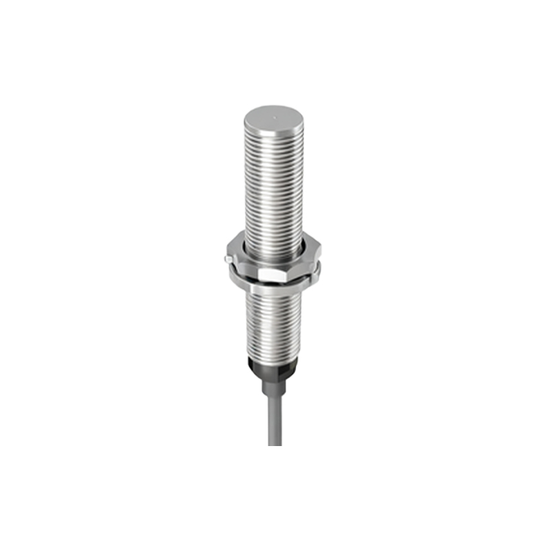
1. Connect the power supply: Attach the positive terminal of the DC power source to the brown wire of the sensor and the negative terminal to the blue wire. This provides the necessary operating voltage for the sensor.
2. Link the sensor output to the relay coil: Connect the black wire (output) of the sensor to one terminal of the relay coil. Then, connect the other coil terminal to the negative side of the power supply (or ground, depending on the circuit design). This creates a control loop where the sensor activates the relay coil when triggered.
3. Wire the load circuit: Connect the high-power load (e.g., a motor) to the relay’s contact terminals. Typically, one contact terminal is connected to the power source for the load, and the other is connected to the load itself. Ensure the relay contacts are rated for the load’s current and voltage requirements.
4. Add protective components: To enhance reliability, consider adding a flyback diode across the relay coil. This diode prevents voltage spikes that can occur when the coil is de-energized, protecting both the sensor and the relay from damage. Also, use fuses or circuit breakers in the load circuit for overcurrent protection.
Once the wiring is complete, test the system by bringing a metal object within the sensor’s sensing range. The relay should click, indicating that the coil is energized, and the load should activate. If the system does not function as expected, double-check all connections, verify power supply polarity, and confirm that the sensor and relay are compatible. Common issues include loose wires, incorrect voltage, or mismatched output types. For troubleshooting, use a multimeter to measure voltages at key points, such as the sensor output and relay coil terminals.
In practical applications, this setup is used in conveyor systems, automated machinery, and safety interlocks. For example, in a packaging line, a proximity sensor can detect when a product is in position, triggering a relay to activate a stamping mechanism. The relay allows the low-current sensor to control a high-current motor without risk of overload. When designing such systems, always adhere to electrical standards and regulations, such as the NEC or IEC guidelines, to ensure safety and compliance.
Moreover, consider environmental factors like temperature, humidity, and electrical noise, which can affect sensor and relay performance. Shielded cables and proper grounding may be necessary in noisy industrial environments. For advanced control, multiple sensors can be connected to a PLC (Programmable Logic Controller) via relays, enabling complex automation sequences. However, the basic principle of interfacing sensors with relays remains the same: using a low-power signal to switch a high-power circuit efficiently.
In summary, wiring a DC proximity switch sensor to a relay is a fundamental skill for electrical engineers in automation. By following proper steps—connecting power, linking the sensor output to the relay coil, and wiring the load with protections—