Proximity sensors are fundamental components in modern industrial automation, providing critical non-contact detection for position sensing, object counting, and safety applications. When a proximity sensor fails to provide a signal, it can halt production lines, cause machine faults, and lead to significant downtime. This guide provides a systematic, engineer-level approach to diagnosing and resolving "no signal" issues in inductive, capacitive, and photoelectric proximity sensors.
The initial step is always safety. Ensure the machine or system is in a safe state—locked out and tagged out (LOTO)—before beginning any physical inspection or testing. Never bypass safety protocols.
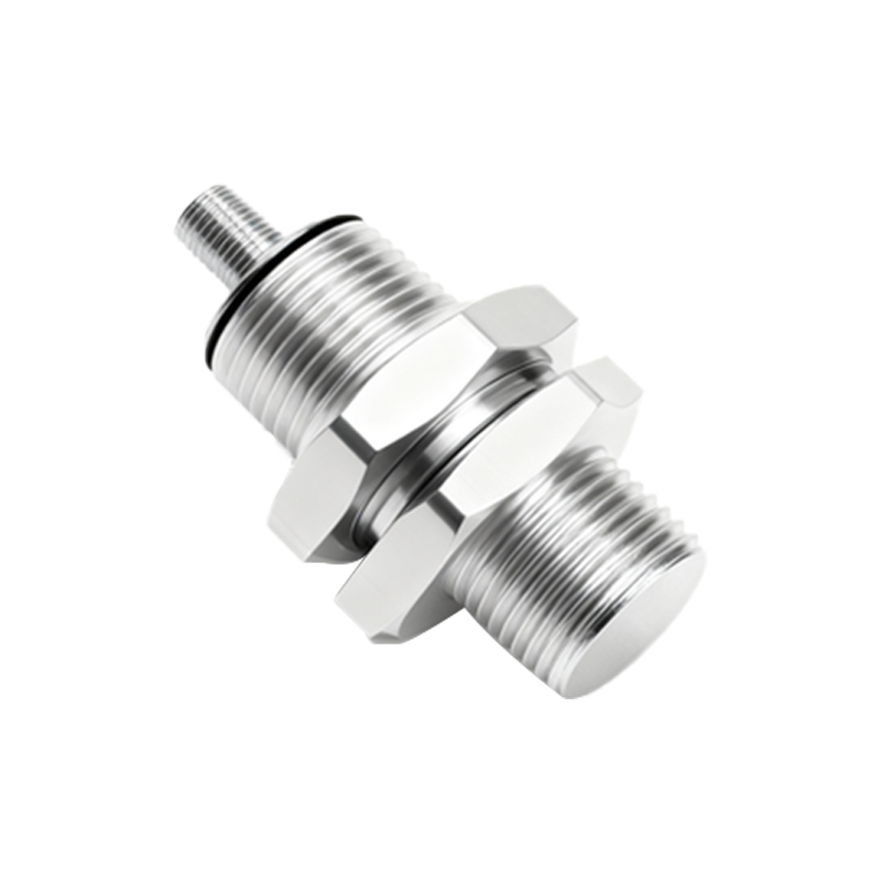
Begin with a visual and physical inspection. Check for obvious signs of damage: cracked housing, bent or broken sensing face, damaged cable or connector, and signs of impact or liquid ingress. Ensure the sensor is securely mounted and that the target is present within its specified sensing range. A common oversight is the use of an incorrect target material for inductive sensors, which only detect ferrous metals. Verify the target's size, material, and approach path meet the sensor's specifications.
Next, verify the electrical connections and power supply. This is the most frequent cause of "no signal" problems.
1. Power Check: Use a multimeter to measure the voltage at the sensor's supply terminals. Ensure it matches the sensor's rated voltage (e.g., 10-30V DC for most DC sensors). A low voltage can prevent the sensor from operating correctly.
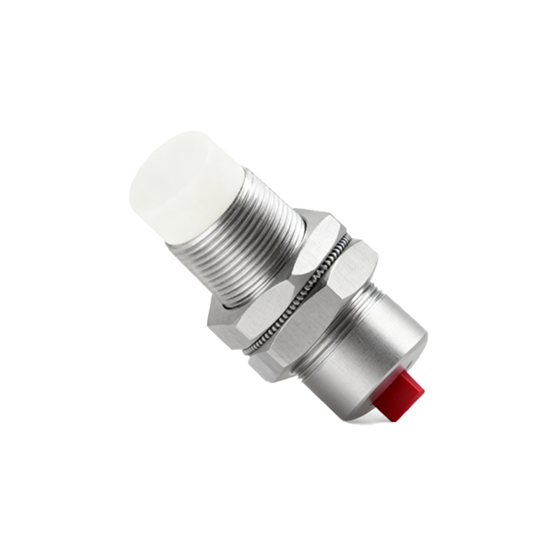
2. Wiring Verification: Consult the sensor's datasheet for its wiring diagram. For a 3-wire DC sensor, typically:
Brown wire: +V (Supply Positive)
Blue wire: 0V (Supply Negative/Common)
Black wire: Signal Output
Ensure wires are connected to the correct PLC input or controller terminal. Check for loose connections, corrosion, or broken wires at both the sensor connector and the control panel terminal block.
3. Load Check: Verify the load (e.g., PLC input, relay coil) connected to the sensor's output is within specifications. Check the load's impedance and current draw. An overloaded or short-circuited output can cause the sensor to shut down or the internal output transistor to fail.
If power and wiring are correct, proceed to output signal testing.
For a switching output sensor, monitor the signal wire voltage relative to common (blue wire). When the target is absent, note the voltage (should be near supply voltage for a PNP normally-open sensor, or near 0V for an NPN). When a valid target is presented, the voltage should switch. No change indicates a faulty sensor or incorrect configuration.
Use an LED indicator if the sensor has one. Most sensors have a built-in LED that illuminates when the target is detected and/or when power is applied. A solid power LED with no switching indicator often points to a sensing issue or internal fault.
Environmental factors are critical. Inductive sensors can be affected by surrounding metals. Ensure there is no metal object (mounting bracket, bolt, machine frame) within the sensor's lateral or axial dead zone, as specified in the manual. For capacitive sensors, changes in humidity, dust, or material buildup on the sensing face can cause false triggering or loss of signal. Clean the sensing face regularly. Photoelectric sensors are susceptible to ambient light interference, dirt on lenses, and misalignment. Use the sensor's sensitivity potentiometer (if available) to adjust for challenging conditions, but avoid over-compensating.
Diagnose by substitution where possible. If a suspected faulty sensor is replaced with a known-good sensor of the same model and the system works, the original sensor is likely defective. Before condemning the sensor, ensure the replacement is configured identically (e.g., NPN vs. PNP, normally-open vs. normally-closed). Some programmable sensors may have their output logic or timing functions altered.
Internal diagnostics of modern sensors can be accessed via IO-Link or other digital interfaces, providing detailed status information like operating voltage, temperature, output switch cycles, and fault codes. Utilize this data for predictive maintenance.
Finally, review the application. The failure may be symptomatic of a larger issue: excessive mechanical vibration loosening connections, repeated physical impact damaging the sensor, washdown procedures forcing water into connectors, or electrical noise from nearby motors and drives inducing signal errors. Implement corrective actions such as improved mounting, conduit seals, or noise suppression ferrites.
A methodical approach—inspecting physical condition, verifying electrical parameters, assessing the environment, and analyzing the application—will efficiently restore signal integrity and minimize unplanned downtime. Always document the fault and solution for future reference.