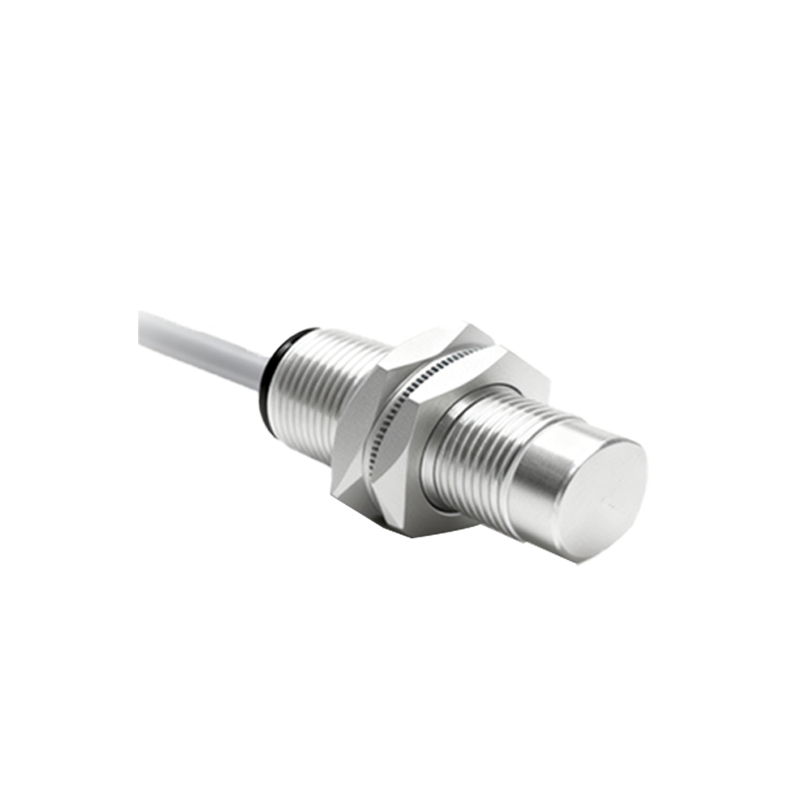
Proximity switch sensors are widely used in industrial automation for detecting the presence or absence of objects without physical contact. Understanding how to wire these sensors in series is crucial for efficient system design, especially in applications where multiple sensors need to interact with a single control input. This guide provides a detailed overview of the series wiring diagram for proximity switch sensors, covering principles, steps, and best practices.
When wiring proximity sensors in series, the primary goal is to connect the output signals of multiple sensors to a single controller input. This configuration is common in safety circuits or logic operations where all sensors must be triggered for a specific action. Typically, proximity sensors come in two types: PNP (sourcing) and NPN (sinking). For series wiring, it is essential to use sensors of the same type to avoid compatibility issues. The wiring diagram involves connecting the output wires of each sensor in a daisy-chain fashion, where the output of the first sensor links to the input of the next, and so on.
To create a series wiring diagram, start by identifying the sensor specifications, including voltage ratings (commonly 12-24V DC), output type, and wire colors (e.g., brown for positive, blue for negative, black for output). Connect the positive supply wire (brown) of the first sensor to the power source's positive terminal. Then, link the negative supply wire (blue) to the power source's negative terminal. For the output connections, wire the black output wire of the first sensor to the black output wire of the second sensor, continuing this pattern for additional sensors. The final output wire from the last sensor should connect to the controller's input terminal. Ensure all connections are secure and insulated to prevent short circuits.
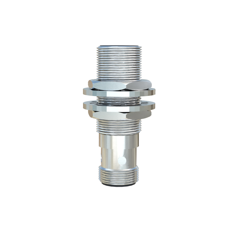
Key considerations include voltage drop and signal integrity. In series wiring, the total resistance increases with each added sensor, potentially causing a voltage drop that may affect sensor performance. To mitigate this, use sensors with low internal resistance and check the power supply capacity. Additionally, verify that the controller input can handle the combined signal current. Testing the circuit with a multimeter is recommended to confirm proper voltage levels and continuity.
Applications of series-wired proximity sensors include conveyor belt systems, where multiple sensors monitor object positions to trigger sequential actions, and safety interlocks in machinery, where all sensors must detect safe conditions before operation. For example, in an automated assembly line, sensors in series can ensure that parts are correctly aligned before a robot arm activates.
Best practices involve labeling wires clearly, using shielded cables in noisy environments to reduce electromagnetic interference, and following manufacturer guidelines for specific sensor models. Regular maintenance, such as checking for loose connections or sensor alignment, helps prevent failures. By mastering series wiring diagrams, engineers can enhance system reliability and optimize automation processes.
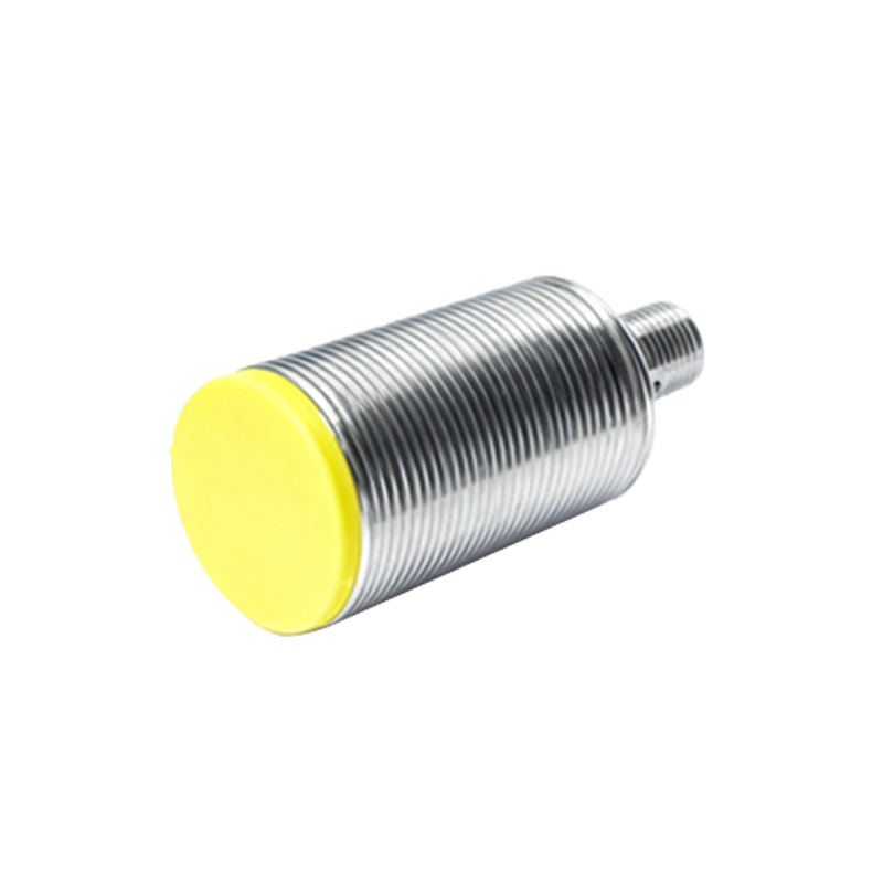
In summary, wiring proximity switch sensors in series is a practical method for consolidating multiple signals into one control point. This approach saves input modules on controllers and simplifies circuit design. Always prioritize safety by disconnecting power during installation and adhering to industry standards like IEC 60947-5-2 for sensor applications. With proper planning and execution, series wiring can improve efficiency in diverse industrial settings.