In modern industrial automation, accurate motor speed measurement is critical for process control, energy efficiency, and predictive maintenance. Among various sensing technologies, proximity sensors have emerged as a robust and reliable solution for monitoring rotational speed in electric motors. These non-contact sensors detect the presence or absence of a target object, typically a metallic component such as a gear tooth, keyway, or dedicated trigger wheel attached to the motor shaft.
The operating principle of inductive proximity sensors, the most common type for this application, is based on electromagnetic induction. The sensor generates an oscillating electromagnetic field. When a ferrous metal target enters this field, eddy currents are induced in the target, causing a change in the oscillation amplitude. This change is detected by the sensor's circuitry, which then switches its output signal. For speed measurement, a series of evenly spaced targets on a rotating element pass by the sensor face. Each detection event generates a pulse. By counting the number of pulses per unit of time, the rotational speed can be precisely calculated using the formula: Speed (RPM) = (Pulses per minute) / (Number of targets per revolution).
Selecting the right proximity sensor involves several key considerations. The sensing distance must be appropriate for the installation gap between the sensor and the target. Factors like target material, size, and shape significantly influence performance; mild steel is the standard reference material. Environmental conditions are paramount. Sensors must be rated for the operating temperature range, resistant to oils, coolants, and washdowns (often requiring an IP67 or IP69K rating), and shielded against electromagnetic interference (EMI) prevalent in motor control centers. Output types are also crucial: a digital PNP or NPN transistor switch is standard, but analog current (4-20 mA) or voltage (0-10 V) outputs can provide continuous signal proportional to distance, useful for eccentricity detection.
Installation and alignment are critical for reliable operation. The sensor must be mounted securely to prevent vibration-induced movement. The target should approach the sensor face perpendicularly to ensure consistent detection. For gear tooth sensing, the sensor is typically aligned with the flank of the tooth, not the tip, to avoid signal variation due to tooth profile. Proper shielding and conduit for cabling are necessary to prevent electrical noise from corrupting the pulse signal, which would lead to inaccurate speed readings.
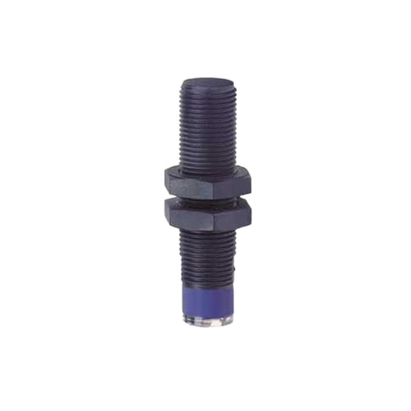
Integrating the sensor signal into the control system is the final step. The pulse train is fed into a high-speed counter input on a Programmable Logic Controller (PLC), a dedicated tachometer module, or a variable frequency drive (VFD). Modern VFDs often have built-in pulse input capabilities for closed-loop speed control. The control system's software calculates the RPM and can trigger alarms for under-speed or over-speed conditions, initiate automated shutdowns for safety, or provide data for maintenance logs.
The advantages of using proximity sensors for motor speed are substantial. Their non-contact nature eliminates mechanical wear, ensuring long service life. They offer high switching frequencies, capable of measuring very high speeds. They are inherently robust, withstanding harsh industrial environments where optical sensors might fail due to dirt or contamination. Furthermore, they provide a simple, cost-effective solution compared to integrated motor encoders, especially for retrofitting existing equipment.
A common application is in conveyor systems, where a sensor monitors a sprocket attached to the drive motor. The speed feedback ensures the conveyor belt maintains the correct velocity for the process. In pump and fan systems controlled by VFDs, a proximity sensor provides verification of actual shaft speed, allowing for precise flow control and detection of cavitation or belt slippage. For large critical motors, such as those in compressors or crushers, multiple sensors can provide redundancy and also enable torsional vibration analysis by examining minute variations in the pulse timing.
In summary, proximity sensors represent a fundamental and highly effective technology for motor speed measurement. Their reliability, durability, and simplicity make them a cornerstone of industrial motor monitoring. Proper selection, installation, and integration are essential to leverage their full potential in enhancing operational efficiency, ensuring safety, and enabling the data-driven practices of modern Industry 4.0 environments.