Magnetic proximity sensors are widely used in industrial automation, robotics, and safety systems due to their non-contact detection capabilities and durability. Proper wiring is crucial for ensuring reliable operation, preventing malfunctions, and extending sensor lifespan. This guide details common wiring methods, key considerations, and best practices for electrical engineers and technicians.
Magnetic proximity sensors typically consist of a sensing head and an electronic circuit. They detect the presence of ferromagnetic objects (like iron or steel) by responding to changes in a magnetic field. Most industrial models are available in two-wire, three-wire, or four-wire configurations, each with distinct wiring requirements.
Two-wire sensors are the simplest to install, as they connect in series with the load (e.g., a PLC input or relay). The sensor acts as a switch, controlling the current flow. When a target object enters the sensing range, the sensor switches states—either opening or closing the circuit. It is essential to verify voltage and current compatibility, as two-wire sensors have a residual current (leakage current) when off, which must be below the load's minimum operating threshold. Incorrect loading can cause failure to switch or unintended activation.
Three-wire sensors are more common in modern control systems. They feature separate power supply wires (typically brown for DC+ or L+ and blue for DC- or N) and a signal output wire (usually black, white, or gray). DC three-wire sensors come in two output types: NPN (sinking) and PNP (sourcing). In NPN configurations, the output switches the negative (ground) side of the load; in PNP, it switches the positive side. Always match the sensor's output type with the controller's input specifications. For AC three-wire sensors, the third wire is often the output signal, while the other two connect to AC line and neutral. Proper grounding and shielding are critical to minimize electrical noise interference, especially in environments with motors or frequency drives.
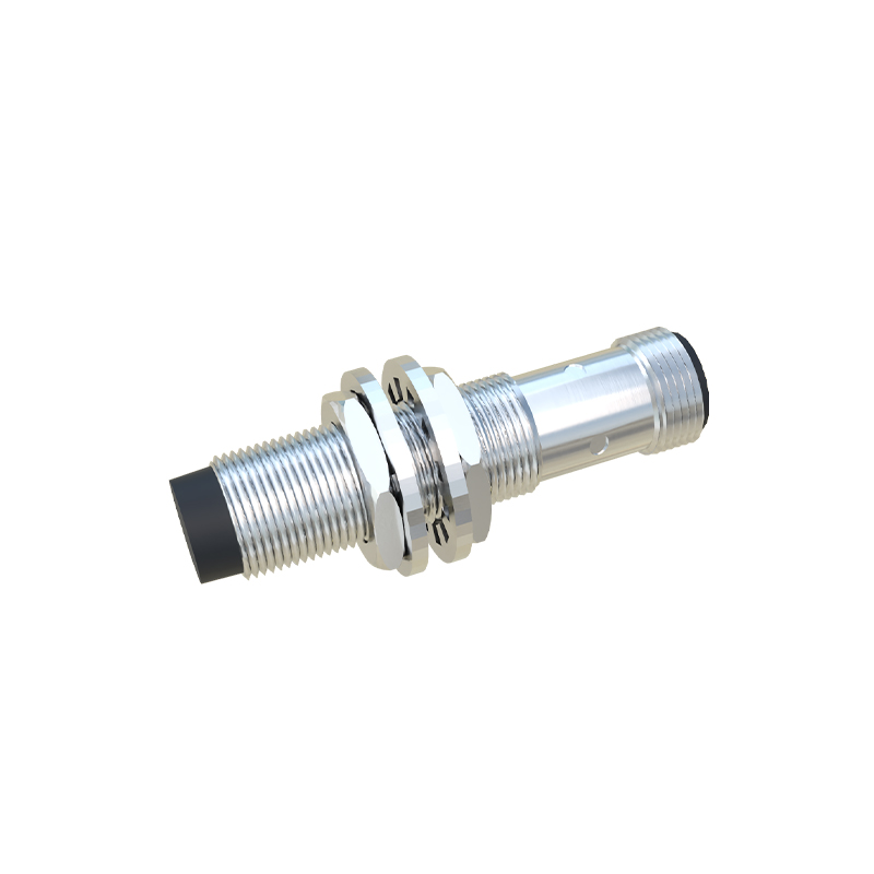
Four-wire sensors typically provide dual outputs (e.g., one NPN and one PNP, or normally open/normally closed contacts). This allows flexible integration into diverse control logic. Wiring follows similar principles to three-wire sensors, with careful attention to datasheet pin assignments. Some four-wire models also include diagnostic LEDs or adjustable sensing ranges, requiring additional connections for configuration.
Key wiring considerations include:
1. Power Supply: Use a stable, regulated power supply within the sensor's rated voltage range (e.g., 10-30 VDC or 90-250 VAC). Voltage spikes or drops can cause erratic behavior.
2. Polarity: For DC sensors, reverse polarity can permanently damage the internal electronics. Always double-check positive and negative connections.
3. Load Matching: Ensure the sensor's output current rating exceeds the load's requirement but does not exceed maximum limits. Inductive loads (like relays) may require surge suppression.
4. Environmental Factors: In harsh conditions (extreme temperatures, moisture, or vibration), use sensors with appropriate IP ratings and consider conduit or shielded cables.
5. Wiring Practices: Use twisted-pair or shielded cables for long runs (>50 meters) to reduce electromagnetic interference. Keep sensor cables away from high-voltage power lines.
Installation steps generally involve:
- De-energizing the circuit before wiring.
- Mounting the sensor securely at the correct distance and orientation relative to the target.
- Connecting wires according to manufacturer diagrams (color codes may vary; always refer to the datasheet).
- Testing with a target object to verify switching behavior and LED indicators (if present).
Common pitfalls include ignoring leakage current in two-wire sensors, mixing NPN/PNP types, and overlooking cable capacitance effects in high-speed applications. For complex systems, consult the sensor's manual and perform functional tests under actual operating conditions.
In summary, correct wiring of magnetic proximity sensors enhances system reliability and safety. By understanding configuration types, adhering to electrical standards, and considering application-specific factors, engineers can optimize sensor performance in automated setups. Regular maintenance and periodic checks further ensure long-term operational integrity.