Proximity sensors are essential components in modern industrial automation, providing non-contact detection of metallic or non-metallic objects. Understanding the correct wiring configuration is critical for ensuring reliable operation, safety, and system integration. This article details the standard wiring diagrams and practical considerations for connecting proximity sensors, particularly focusing on common 3-wire and 4-wire DC models prevalent in industrial settings.
A proximity sensor typically operates by generating an electromagnetic field. When a target object enters this field, it causes a change in the oscillation amplitude, which is detected by the sensor's circuit, triggering an output signal. The wiring connects this internal circuitry to a power supply and a control system, such as a Programmable Logic Controller (PLC).
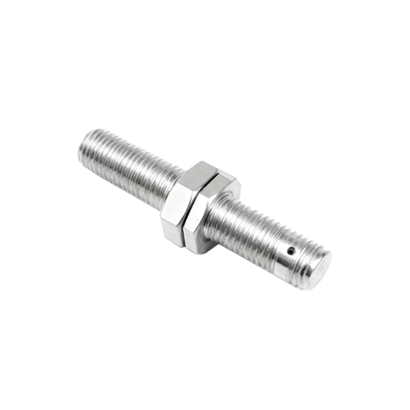
The most fundamental distinction in wiring is between 2-wire, 3-wire, and 4-wire sensors. Two-wire AC sensors are simple, connecting in series with the load, but have limitations in leakage current. For precision DC applications, 3-wire sensors are the industry standard. They consist of three leads: brown (or red) for the positive supply voltage (+V), blue (or black) for the common negative (0V), and black (or white) for the output signal. The output can be either NPN (sinking) or PNP (sourcing). An NPN sensor switches the negative (0V) line to the load, meaning the load is connected between the sensor's output and the positive supply. Conversely, a PNP sensor switches the positive voltage to the load, with the load connected between the output and common negative. Misidentifying NPN vs. PNP is a common installation error that prevents proper operation.
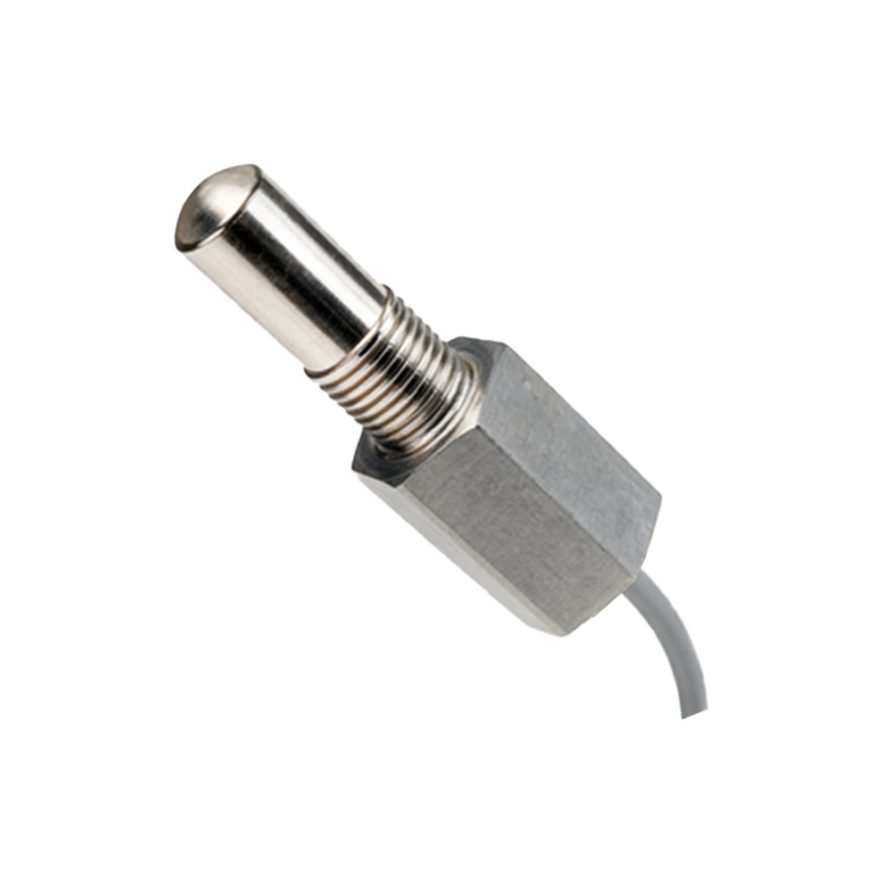
A standard 3-wire DC proximity sensor wiring diagram follows this pattern: The brown wire is connected to the positive terminal of a 10-30V DC power supply. The blue wire is connected to the negative terminal of the same supply and also to the common (0V) of the PLC's input module. The black output wire is then connected to the specific input channel on the PLC. For a PNP sensor, the PLC input is typically configured as a sinking input. For an NPN sensor, the PLC input is configured as a sourcing input. It is paramount to verify the sensor's datasheet and the PLC's input specifications to ensure compatibility.
Four-wire sensors typically provide two separate outputs, often one Normally Open (NO) and one Normally Closed (NC) contact, or sometimes two independent outputs of the same type (e.g., dual PNP). The wiring is an extension of the 3-wire principle: brown (+V), blue (0V), black (Output 1), and white (Output 2). This configuration offers greater flexibility for control logic, allowing a single sensor to trigger two different actions or provide a fail-safe signal.
Shielded cable is highly recommended for long cable runs or in electrically noisy environments. The cable shield should be grounded at only one end, typically at the control panel, to prevent ground loops. Always adhere to the manufacturer's specified voltage range and current limits. Overvoltage or incorrect polarity can instantly damage the sensor's electronics. For inductive sensors detecting metals, ensure the sensing face has adequate clearance from surrounding metal objects to avoid false triggering.
A practical wiring example involves integrating a PNP inductive proximity sensor with a PLC to detect a machine part. The brown wire connects to +24VDC. The blue wire connects to the 0VDC and the PLC common. The black wire connects to PLC input I0.0. When a metal part approaches, the sensor activates, sending +24V to the PLC input, which the PLC program interprets as a true condition. For an NPN sensor in the same setup, the black wire would still connect to I0.0, but the PLC input's internal circuit would be wired to +24VDC, expecting the sensor to complete the circuit to 0V.
In conclusion, correct wiring is not merely a matter of connecting colored wires. It requires understanding the sensor's output type (NPN/PNP), the power supply characteristics, and the input requirements of the controlling device. Always reference the official wiring diagram provided in the sensor's technical documentation. Proper installation ensures optimal performance, minimizes downtime, and upholds the safety standards required in industrial automation systems. Pre-wiring checks with a multimeter for continuity and correct voltage can prevent costly errors and equipment damage.