This comprehensive user manual provides detailed technical information, installation guidelines, operational procedures, and maintenance instructions for the SQX Series Square Proximity Sensors. Designed for industrial automation applications, these robust sensors offer reliable non-contact detection of metallic objects.
1. Product Overview
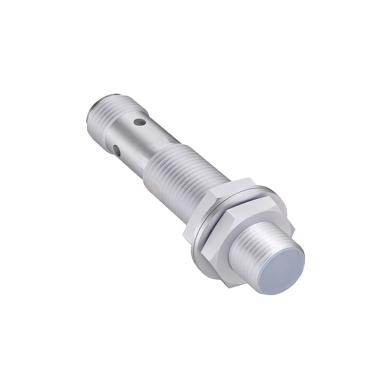
The SQX Series Square Proximity Sensor is a solid-state electronic device engineered for precise position sensing in demanding industrial environments. Utilizing an electromagnetic field, it detects the presence of ferrous and non-ferrous metallic targets without physical contact, thereby eliminating mechanical wear and ensuring long service life. The compact, square housing (typically constructed from nickel-plated brass or stainless steel) provides enhanced resistance to impacts, vibrations, and harsh conditions commonly found in manufacturing, packaging, and material handling systems.
2. Technical Specifications
Sensing Principle: Inductive
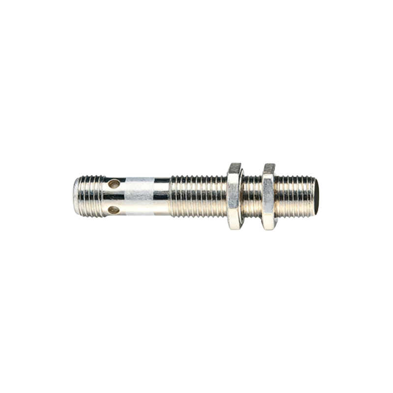
Housing Material: Nickel-plated brass (Standard), Stainless steel (Heavy-duty variant)
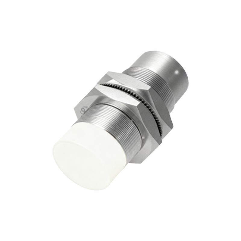
Protection Rating: IP67 (IEC 60529), ensuring protection against dust and temporary immersion.
Output Configuration: Available in NPN (sinking) or PNP (sourcing) DC configurations. Selectable normally open (NO) or normally closed (NC) operation.
Supply Voltage: 10-30 VDC, ripple (p-p) ≤ 10%.
Output Current: Maximum 200mA. Short-circuit and overload protection are integrated.
Sensing Distance (Sn): Ranges from 2mm to 15mm, depending on model. Refer to model-specific datasheet. This rated operating distance is calibrated for a standard mild steel target (Fe 360).
Hysteresis: ≤ 10% of Sn (typical), ensuring stable switching and prevention of chatter.
Response Frequency: Up to 1.5 kHz, suitable for high-speed counting and detection applications.
Ambient Temperature Range: Operation: -25°C to +70°C. Storage: -40°C to +85°C.
Indicator LED: Red LED for output status indication.
Connection: Pre-wired cable (2m standard) or quick-disconnect M8 or M12 connector options.
3. Installation and Wiring
Mounting:
Ensure the sensor is mounted securely using appropriate hardware. Maintain the recommended clearance around the sensing face: a minimum of 2Sn from adjacent metal surfaces (side and rear) to prevent false triggering. For flush-mountable types, they can be embedded in metal without affecting performance. Non-flush models require a free zone around the sensing face.
Wiring:
Disconnect power before installation. Standard 3-wire connection is as follows:
Brown Wire (BN): Connect to positive DC supply voltage (+V).
Blue Wire (BU): Connect to negative DC supply voltage (0V / GND).
Black Wire (BK): Load output wire. Connect to your PLC input, relay, or controller.
For PNP sensors: The black wire sources current to the load. The load is connected between BK and 0V.
For NPN sensors: The black wire sinks current from the load. The load is connected between +V and BK.
Always adhere to local electrical codes and standards. Use shielded cables in electrically noisy environments, grounding the shield at the controller end only.
4. Operation and Sensing Characteristics
The sensor's active face generates an oscillating electromagnetic field. When a metallic target enters this field, eddy currents are induced, causing a change in the oscillation amplitude. The sensor's internal circuit detects this change and switches the solid-state output.
Target Material: Sensing distance varies with target material. For non-ferrous metals like aluminum, brass, or copper, the effective sensing distance is reduced. A correction factor (provided in the datasheet) must be applied.
Target Size: The target should be equal to or larger than the sensor's sensing face for guaranteed detection at the rated distance (Sn).
Approach Direction: The target should approach the sensor perpendicular to the sensing face for optimal performance.
5. Diagnostics and Troubleshooting
LED Continuously On: Possible causes: Sensor is in detection range, wiring error (e.g., load connected incorrectly), internal fault.
LED Off: Possible causes: No power supply, broken wire, supply voltage outside range, sensor damaged.
LED On, No Output Signal: Possible causes: Output overload (exceeds 200mA), load is open-circuit, output transistor failure.
Intermittent Operation: Check for unstable power supply, insufficient target size, target moving too fast,