In the realm of industrial automation, proximity sensor switches are the unsung heroes, providing critical non-contact detection for countless processes. Among these, the M80 series is a widely recognized and reliable workhorse. However, like all electromechanical components, M80 proximity sensors are susceptible to failure. Understanding the common failure modes, their symptoms, and effective troubleshooting steps is paramount for minimizing downtime and maintaining operational efficiency.
A proximity sensor, fundamentally, detects the presence or absence of a metallic target without physical contact. The M80, typically an inductive type, generates an electromagnetic field. When a metal object enters this field, it causes a change in the oscillation amplitude, which the sensor's circuitry detects and converts into a switching signal. Failures can originate from the sensor itself, its installation, the target, or the connected load and power supply.
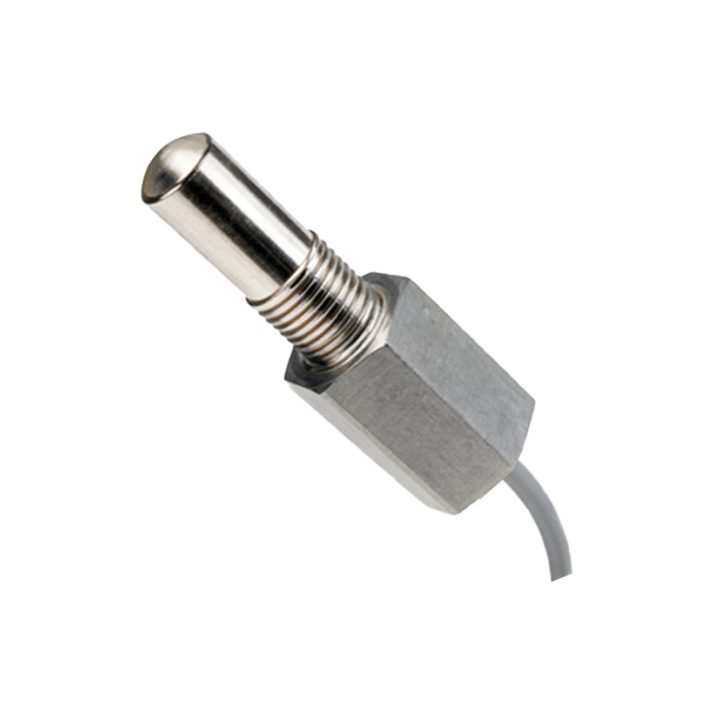
One of the most prevalent issues is mechanical damage. The M80's housing, though robust, can be compromised by direct impact, excessive vibration, or crushing forces in harsh environments. This can lead to cracked casings, damaged sensing faces, or internal component displacement. Symptoms include complete non-operation or intermittent signal loss. Visual inspection is the first line of defense. Ensure the sensor body is intact and free from deep scratches or deformities on the active surface.
Electrical overload and wiring faults constitute another major category. Despite built-in protection, sustained short circuits, incorrect voltage supply (e.g., applying 24VDC to a 120VAC model), or reverse polarity can fry the internal electronics. Similarly, loose connections, corroded terminals, or damaged cable insulation can cause erratic behavior. Always verify the power supply voltage and polarity with a multimeter. Check for tight wire terminations and inspect the cable along its entire length, especially at strain relief points. Remember, the brown wire is typically positive (+), blue is negative/common (-), and black is the output signal.
Environmental factors are silent killers. The ingress of coolants, oils, metal chips, or conductive dust can coat the sensing face or penetrate the housing, leading to internal short circuits or degraded performance. While many M80 models are rated IP67, prolonged exposure to aggressive chemicals or extreme temperatures beyond its specification (e.g., -25°C to +70°C) can degrade seals and components. Regularly clean the sensor face with a soft cloth. Ensure the operating environment stays within the sensor's rated temperature, humidity, and media compatibility ranges.
Incorrect installation and setup often mimic sensor failure. The sensing distance of an inductive M80 sensor is nominal and can be affected by the target material (steel is optimal, aluminum and brass have reduced ranges), target size, and approach direction. Installing the sensor too far from the target or using an undersized target will cause failure to detect. Furthermore, sensors mounted in close proximity to each other can cause mutual interference (crosstalk), leading to false triggering. Adhere to the manufacturer's specified mounting distances, target specifications, and minimum separation distances between adjacent sensors.
Internal component degradation over time is inevitable. The oscillator, output switching transistor, or voltage regulator can wear out after millions of operating cycles. This usually manifests as a gradual decline in performance—a shrinking effective sensing range or an output that cannot properly drive the load. A simple test involves using a known-good target and gradually moving it toward the sensor face while monitoring the output with a multimeter or PLC input indicator. Compare the actual switching point to the rated sensing distance.
A systematic troubleshooting approach is recommended:
1. Observe: Note the exact symptom (no signal, constant signal, intermittent signal).
2. Inspect: Perform a visual and mechanical check for damage and cleanliness.
3. Verify Power & Wiring: Confirm correct voltage at the sensor terminals and check wiring integrity.
4. Isolate: Temporarily connect the sensor to a simple test circuit (e.g., a lamp) to rule out issues with the PLC or downstream controller.
5. Test with Target: Use a standard target to check sensing performance.
6. Check Environment: Review ambient conditions against the sensor's datasheet ratings.
Proactive maintenance, including regular inspection, proper installation, and environmental control, significantly extends the service life of M80 proximity switches. When replacement is necessary, always cross-reference the exact model number, noting its type (NPN/PNP), output configuration (NO/NC), voltage, and thread size (e.g., M8 x 1 or M12 x 1). Keeping a few calibrated spares on hand is a best practice that can save hours of costly production downtime.