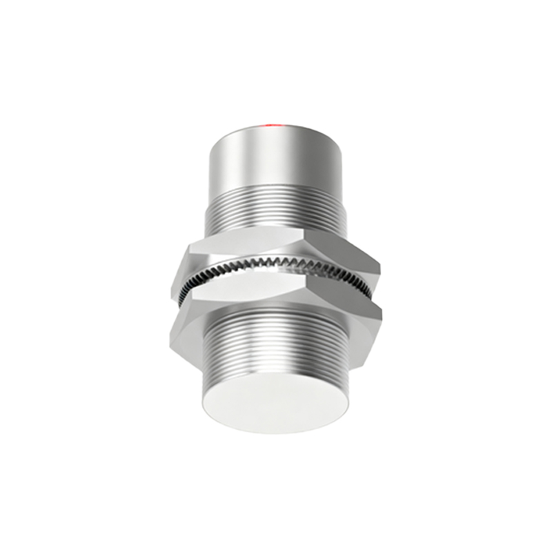
Proximity sensors are essential components in modern industrial automation, robotics, and safety systems. Their ability to detect the presence or absence of an object without physical contact makes them invaluable across various applications. Understanding the structure of a proximity sensor is key to selecting, installing, and maintaining these devices effectively. While designs vary based on sensing technology—such as inductive, capacitive, ultrasonic, or photoelectric—the core structural principles share common elements.
At the heart of most proximity sensors lies the sensing element or oscillator circuit. In an inductive proximity sensor, this typically involves a coil wound around a ferrite core, which generates an oscillating electromagnetic field. When a metallic target enters this field, eddy currents are induced, causing a change in oscillation amplitude or frequency. This change is detected by the sensor's circuitry. The coil and core are housed within a protective casing, often made of materials like nickel-plated brass, stainless steel, or engineering plastics like PBT or PPS, chosen for durability and resistance to environmental factors like moisture, chemicals, and mechanical impact.
Surrounding the sensing element is the electronic processing unit. This includes an oscillator to generate the high-frequency field, a demodulator to convert the amplitude changes into a DC signal, a trigger circuit to set the detection threshold, and an output stage. The output stage can be solid-state (like NPN or PNP transistors) or relay-based, providing a switching signal to control external devices. Modern sensors often integrate microcontrollers for advanced functions such as programmability, diagnostics, and communication via IO-Link or other industrial protocols.
The front face of the sensor, known as the sensing face or active surface, is critical. It is usually made of a non-metallic material (e.g., plastic or ceramic) in inductive sensors to allow the electromagnetic field to propagate, while capacitive sensors may use metallic faces. The design ensures optimal field projection and protects internal components. Some sensors feature flush-mount or non-flush-mount designs, affecting their installation and sensing range.
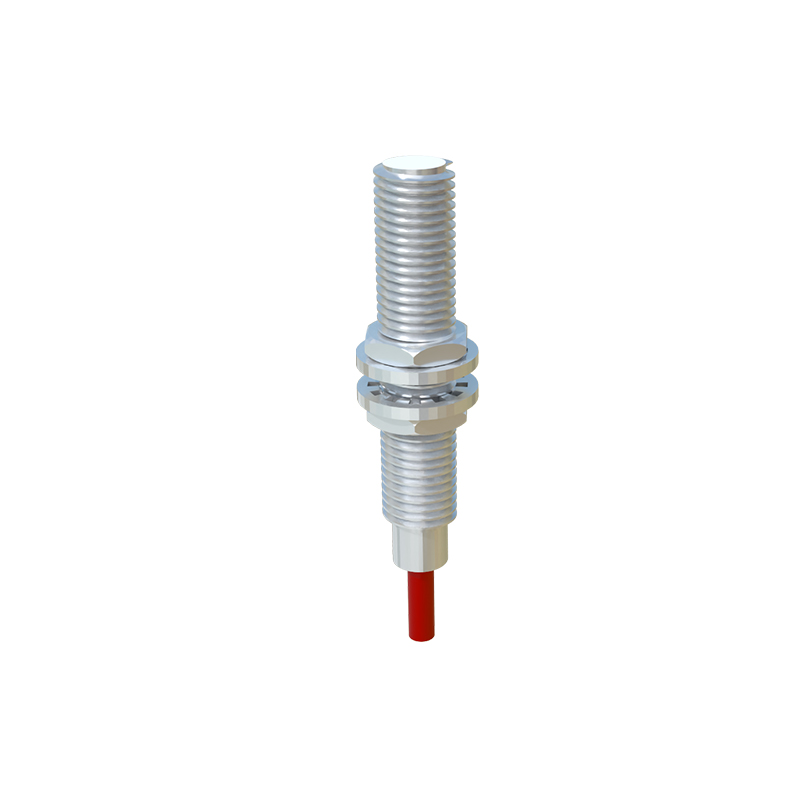
Housing and connectivity form the external structure. The housing provides IP (Ingress Protection) ratings, such as IP67 or IP69K, for dust and water resistance. It includes threaded barrels (e.g., M8, M12, M18, M30) for easy mounting in industrial settings. Electrical connections are made via pre-wired cables or quick-disconnect connectors, often color-coded or labeled for voltage input, output, and ground. LEDs for status indication (power, output, diagnostics) are commonly embedded in the housing.
Additional structural features may include sensing range adjusters, shielding to reduce electromagnetic interference, and temperature compensation circuits for stable operation in varying conditions. For example, ultrasonic sensors incorporate a piezoelectric transducer for sound wave emission and reception, housed with acoustic damping materials to minimize noise.
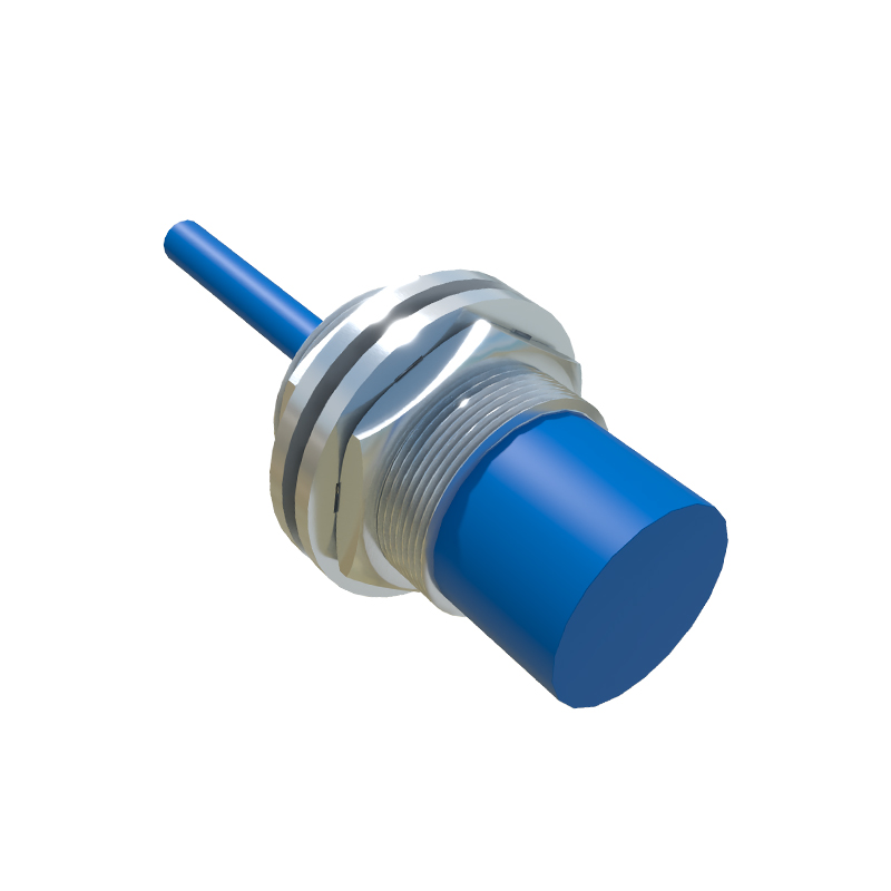
In summary, the structure of a proximity sensor integrates electromagnetic or acoustic components, signal processing electronics, robust housing, and connectivity interfaces. This design ensures reliable, non-contact detection in demanding environments, from factory floors to outdoor applications. Proper understanding of these structural aspects enables engineers to optimize sensor performance, enhance system safety, and reduce downtime in automated processes.