In industrial automation and control systems, the integration of proximity sensors with contactors is a fundamental yet critical task. A proximity sensor detects the presence or absence of an object without physical contact, while a contactor is an electrically controlled switch used for switching a power circuit. Properly connecting these two components ensures reliable machine operation, safety, and system longevity. This guide provides a detailed, professional procedure for wiring a typical 3-wire DC proximity sensor to a standard AC contactor.
First, it is imperative to understand the specifications of both devices. Proximity sensors commonly come in two types based on output: NPN (sinking) and PNP (sourcing). For this guide, we will use a widely adopted 3-wire DC PNP sensor. The three wires are typically color-coded: brown for positive supply (+V), blue for common negative (0V), and black for the switched output signal. The contactor has a main power circuit (line and load terminals) and a control coil (usually labeled A1 and A2). The coil voltage must match the control circuit voltage, which, in this setup, will be provided by the same DC supply powering the sensor.
Step 1: Safety and Preparation
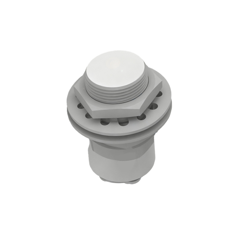
Always de-energize the entire control circuit and lock out/tag out (LOTO) the power source before beginning any wiring work. Verify the sensor and contactor ratings (voltage, current) against your schematic and power supply. Gather necessary tools: wire strippers, screwdrivers, ferrules, and appropriate gauge wires. Ensure the DC power supply voltage (e.g., 24V DC) matches both the sensor's operating voltage and the contactor coil voltage.
Step 2: Power Supply Connections
Connect the DC power supply. Run a wire from the positive terminal (+) of the 24V DC supply to the brown wire of the proximity sensor. Run a wire from the negative terminal (-) of the supply to the blue wire of the sensor. This provides operating power to the sensor. Next, connect this same negative supply line to one terminal of the contactor's coil (terminal A2 is commonly used as the common connection). Use secure terminal blocks or direct connections, ensuring tight and clean terminations.
Step 3: Sensor Output to Contactor Coil
This is the core control connection. The black wire from the PNP proximity sensor is the output. When the sensor detects a target, it switches this output line to supply +24V DC. Connect this black wire to the remaining coil terminal of the contactor (terminal A1). Now, the circuit is complete: DC supply (+) -> sensor (brown) -> sensor internal switch -> sensor output (black) -> contactor coil (A1) -> contactor coil (A2) -> DC supply (-). When the sensor activates, current flows through the coil, creating a magnetic field that pulls in the contactor's main contacts.
Step 4: Main Power Circuit and Load
The contactor's main power terminals (e.g., L1, L2, L3 for three-phase; or L1 and T1 for single-phase) are wired independently. Connect the incoming line power (e.g., 480V AC) to the line terminals. Connect the wires leading to your load (e.g., a motor, heater) to the load terminals. The control circuit (sensor and coil) is completely isolated from this high-voltage power circuit, which is a key safety feature.
Step 5: Testing and Verification
Before applying main power, double-check all wiring against a diagram. Temporarily apply only the 24V DC control power. Place a metal target within the sensing range of the proximity sensor. You should hear a distinct click from the contactor as its coil energizes and the main contacts close. Use a multimeter in continuity or voltage mode to verify that the main contacts close when the sensor is activated. Once the low-voltage control operation is confirmed, you can safely energize the main power circuit for final functional testing.
Important Considerations and Best Practices:
1. Flyback Diode/Suppressor: For DC coils, always install a flyback diode (reverse-biased) across the coil terminals (A1-A2) to suppress voltage spikes generated when the coil de-energizes, protecting the sensor's solid-state output.
2. Sensor Type (NPN vs. PNP): If using an NPN sensor, the wiring differs. The black output wire switches the negative side. In that case, connect the blue wire to DC negative, brown to DC positive, and the black wire to the contactor coil's A1 terminal. Then, connect the other coil terminal A2