Proximity switch sensors are indispensable components in modern industrial automation, providing non-contact detection of metallic and, in some cases, non-metallic objects. Their reliability hinges not only on the sensor itself but also on the correct installation and wiring. A clear, accurate wiring diagram is the cornerstone of a functional and safe sensor system. This guide details the standard wiring configurations for common types of proximity sensors, focusing on the critical role of the sensor cable and harness.
The core of any proximity sensor wiring involves three or four primary conductors, typically color-coded to international standards (IEC 60947-5-2). The most common configuration for a 3-wire DC sensor includes: a brown wire for the positive supply voltage (+V, often 10-30V DC), a blue wire for the common negative or 0V, and a black wire for the switched output signal. For a PNP (sourcing) sensor, the black output wire switches the positive voltage to the load. Conversely, for an NPN (sinking) sensor, the black output wire switches the negative path to the load. A 4-wire DC sensor typically adds a second output wire (often white) to provide both normally open (NO) and normally closed (NC) switching functions from the same device.
The wiring harness, or cable assembly, is far more than just a bundle of wires. It is an engineered component designed for the harsh industrial environment. A quality sensor cable features oil-resistant, PVC or PUR outer sheathing for mechanical durability and chemical protection. Internally, individually shielded pairs may be used to minimize electromagnetic interference (EMI) from nearby motors, variable frequency drives (VFDs), or power lines, which can cause erratic sensor behavior. The cable's termination is equally critical. Most industrial proximity sensors use a quick-disconnect (QD) or M12-style circular connector. These connectors are rated for IP67 or higher, ensuring a dust-tight and waterproof seal when properly mated. The wiring diagram must specify the pin-out for these connectors, matching the wire color to the pin number (e.g., Pin 1: Brown (+V), Pin 2: Black (Output), Pin 3: Blue (0V)).
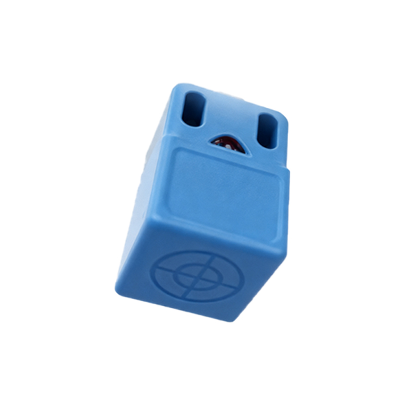
When interpreting or creating a wiring diagram, always begin by verifying the sensor specifications: operating voltage (DC or AC), output type (PNP/NPN, NO/NC), and current rating. The diagram should clearly show the complete circuit path. For a typical PNP sensor connection to a Programmable Logic Controller (PLC) digital input, the brown wire connects to the DC positive terminal, the blue wire to the DC common/negative, and the black output wire connects to the PLC input terminal. The PLC input itself is internally connected to the common negative, completing the circuit. It is paramount to include protective devices in the diagram. A fuse (1-2A) on the positive supply line protects against short circuits. In environments with high inductive loads (like solenoids or relays) connected to the sensor output, a flyback or clamping diode across the load is recommended to suppress voltage spikes that can damage the sensor's solid-state output.
For AC (two-wire) proximity sensors, the wiring is simpler but requires careful consideration of the residual current. The two wires are connected in series with the load and the AC power supply. A crucial element often shown in the diagram is a shunt resistor or a bypass device, which may be necessary to ensure the sensor receives enough holding current to remain operational when off, preventing leakage current from falsely activating the load.
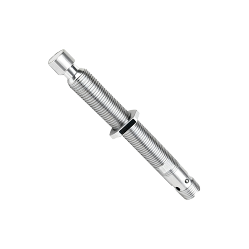
Best practices for wiring harness installation include using continuous cable runs from the sensor to the junction box or controller whenever possible. If a splice is unavoidable, it must be made within a sealed enclosure. Cables should be routed away from high-power lines, using separate cable trays or conduits. Maintain proper bend radii to avoid damaging the internal conductors and shield. Always follow the manufacturer's provided wiring diagram, as color codes, especially for specialized sensors or specific brands, can vary. Properly executed wiring, guided by a precise diagram, ensures maximum sensor performance, reduces electromagnetic compatibility (EMC) issues, and minimizes costly downtime in automated production systems.