In the realm of industrial automation and control systems, proximity sensors are indispensable components for detecting the presence or absence of objects without physical contact. Their reliability and versatility make them a cornerstone in machinery, assembly lines, and safety systems. A fundamental aspect of integrating these sensors into a control circuit is understanding their electrical wiring, specifically the type of output transistor used. Primarily, proximity sensor wiring configurations are categorized into two distinct types: NPN and PNP. This distinction is crucial for ensuring compatibility with Programmable Logic Controllers (PLCs), relays, and other control devices.
The core difference between NPN and PSNP sensors lies in the type of transistor used for switching the output signal and the resulting current flow path. This is not a matter of sensor quality or detection technology (inductive, capacitive, or photoelectric), but rather the electrical interface they provide.
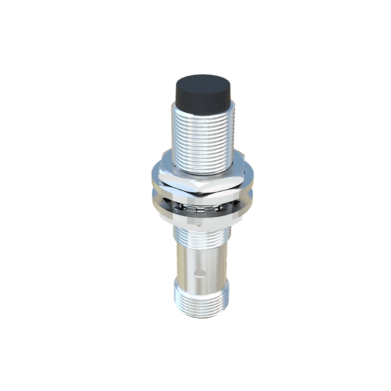
NPN Wiring Configuration (Sinking Output)
An NPN proximity sensor utilizes a Negative-Positive-Negative transistor at its output stage. In this configuration, the output acts as a switch that connects the load to the negative voltage supply (common or 0V). When the sensor is inactive (no target detected), the output transistor is off, and the output terminal is in a high-impedance state. Upon detecting a target, the NPN transistor turns on, effectively "sinking" current from the load into the sensor's output terminal and then out through its common wire to the negative supply.
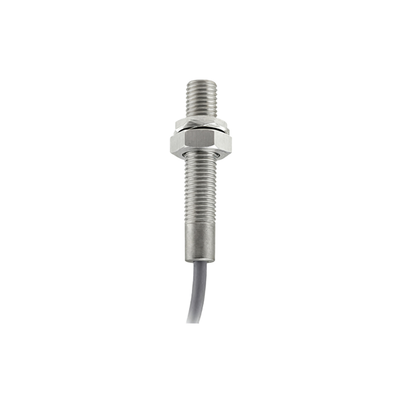
A typical wiring setup involves:
Connecting the sensor's Brown wire (typically +V, e.g., +24V DC) to the positive power supply.
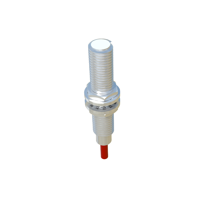
Connecting the sensor's Blue wire (typically 0V or common) to the negative power supply.
Connecting the sensor's Black wire (output signal) to one terminal of the load (e.g., a PLC input module).
The other terminal of the load is then connected to the positive power supply.
Thus, when activated, current flows from the positive supply, through the load, into the sensor's black wire, and out through the blue wire to negative. This is why NPN outputs are often called "sinking" outputs; they sink current into themselves to complete the circuit. This configuration is historically common in regions like Asia and is compatible with PLCs designed for sinking inputs.
PNP Wiring Configuration (Sourcing Output)
A PNP proximity sensor employs a Positive-Negative-Positive transistor. Here, the output switch connects the load to the positive voltage supply. When inactive, the output is again in a high-impedance state. When a target is detected, the PNP transistor turns on, "sourcing" current from the sensor's output terminal to the load.
A typical wiring setup involves:
Connecting the sensor's Brown wire (+V) to the positive power supply.
Connecting the sensor's Blue wire (0V) to the negative power supply.
Connecting the sensor's Black wire (output signal) to one terminal of the load.
The other terminal of the load is then connected to the negative power supply.
Therefore, when activated, current flows from the positive supply, through the sensor's internal transistor and out the black wire, through the load, and finally to the negative supply. PNP outputs are termed "sourcing" outputs because they source current from themselves to power the load. This wiring is prevalent in Europe and North America and pairs with PLCs configured for sourcing inputs.
Key Considerations for Selection
Choosing between NPN and PNP is primarily dictated by the control system's input module design. One must consult the PLC or controller manual. Mismatching can lead to the device not functioning or potential damage. A simple rule of thumb: A PNP sensor provides a positive signal (+V) when active, while an NPN sensor provides a path to ground (0V) when active.
Another critical concept is the "normally open" (NO) or "normally closed" (NC) switching logic, which is independent of the NPN/PNP choice. An NO sensor conducts (closes the switch) when a target is detected. An NC sensor stops conducting (opens the switch) when a target is detected. One can have an NPN-NO, NPN-NC, PNP-NO, or PNP-NC sensor.
For wiring, always adhere to the manufacturer's datasheet for wire color codes and ratings, as conventions can vary (though brown/blue/black is a widespread DC standard). Ensure correct voltage polarity and use shielded cables in electrically noisy environments. Proper grounding of the sensor body and cable shield is essential for stable operation.
In summary, the dichotomy of NPN (sinking) and PNP (sourcing) wiring forms the bedrock of connecting