A 24V proximity sensor is a cornerstone of modern industrial automation, providing non-contact detection of metallic objects in machinery, conveyor systems, and robotic cells. When one fails, it can halt production lines and cause costly downtime. As an experienced electrical engineer, I've repaired countless sensors and can affirm that many failures are repairable with systematic troubleshooting. This guide details a professional approach to diagnosing and fixing common issues in 24V DC inductive proximity sensors.
Before any repair, adhere to strict safety protocols. De-energize the circuit, lock out and tag out (LOTO) the power source, and verify the absence of voltage with a multimeter. Wear appropriate personal protective equipment (PPE). Gather your tools: a digital multimeter (DMM), oscilloscope (optional for advanced diagnosis), soldering iron, desoldering pump, isopropyl alcohol, clean lint-free cloths, and possibly a replacement sensor datasheet for reference.
The first step is accurate diagnosis. A sensor malfunction often manifests as no output signal, intermittent operation, or reduced sensing range. Begin with a visual inspection. Examine the sensor housing for cracks, dents, or signs of impact. Check the cable entry point for strain or cuts, and inspect the sensing face for accumulation of metal shavings, dirt, or grease, which can severely attenuate its field. Clean the face thoroughly with isopropyl alcohol.
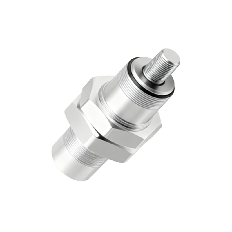
Next, perform electrical tests with the sensor disconnected. Using your DMM, check the cable and connector for continuity and short circuits. Measure resistance between the individual wires (typically brown for +24V, blue for 0V, and black for the output). An infinite reading between wires is normal; a low resistance indicates an internal short. Check for continuity between each wire and the sensor's metal housing to rule out a ground fault.
Now, power the sensor from a bench 24V DC supply. Connect the brown wire to positive and blue to negative. With no target present, measure the voltage between the black output wire and the negative terminal. For a normally open (NO) sensor, you should read close to the supply voltage (high state). Bring a piece of mild steel, the standard target material, within the specified sensing distance. The output voltage should drop to near 0V (low state) for a sinking (NPN) output, or rise for a sourcing (PNP) type. If the output does not switch, the internal oscillator or output switching circuit is likely faulty.
For sensors with a switching output but a reduced sensing range, the issue often lies in the oscillator circuit components. The core of an inductive sensor is a coil that generates a high-frequency electromagnetic field. Over time, thermal stress or voltage transients can degrade the oscillator transistor, resonant capacitor, or the coil itself. With the sensor powered, you can use an oscilloscope to probe the coil terminals (usually inaccessible without disassembly) to see if the oscillation amplitude has diminished.

If electrical tests point to an internal fault, proceed with physical disassembly. Many industrial sensors are potted with epoxy resin to protect against vibration and moisture, making repair impractical. However, some models with threaded barrels have a rear compartment containing the electronics. Carefully unscrew the back cover. Avoid damaging the O-ring seal.
Inside, you will typically find a small PCB. Inspect it for burnt components, cracked solder joints, or corroded traces. Pay special attention to the output transistor (often a MOSFET) and the voltage regulator. Use your DMM in diode mode to test these semiconductors. Desolder and replace any visibly damaged or electrically faulty components with exact or suitable substitutes. For instance, a common failure is the suppression diode across the coil or the output protection diode; replacing these can restore function. If the coil is open or shorted, repair is usually not feasible unless you have an identical coil for replacement.
After component replacement, reassemble the sensor. Ensure all seals are clean and properly seated to maintain the IP rating. Before reinstalling, repeat the bench electrical test. Verify the sensing distance with a target. It should meet or come close to the original specifications. A slight reduction may be acceptable for non-critical applications.
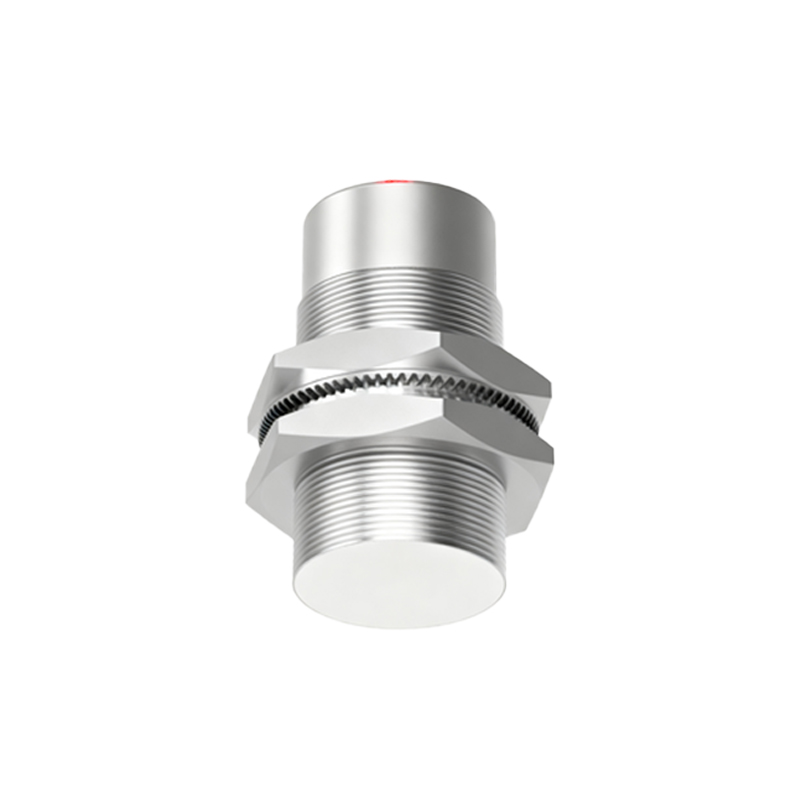
Finally, reinstall the sensor in its application. Ensure proper alignment with the target, secure mounting, and correct wiring. Power the system and perform several operational cycles to confirm reliable detection. Monitor the sensor's temperature; excessive heat suggests remaining issues.
Preventive maintenance is key. Regularly clean sensor faces, check cable integrity, and ensure electrical connections are tight. Use surge protectors on the supply line to guard against voltage spikes. While not every potted sensor can be saved, this methodical repair approach can salvage many units, reducing waste and saving significant costs in industrial environments. Remember,