In industrial automation systems, photoelectric proximity sensors are indispensable components for non-contact object detection. Their integration with Programmable Logic Controllers (PLCs) forms the backbone of countless control sequences, from packaging lines to robotic assembly cells. Correct wiring is paramount for reliable operation, safety, and system longevity. This guide details the standard wiring methodologies for connecting common types of photoelectric sensors to a PLC's digital input module.
Understanding the Core Components
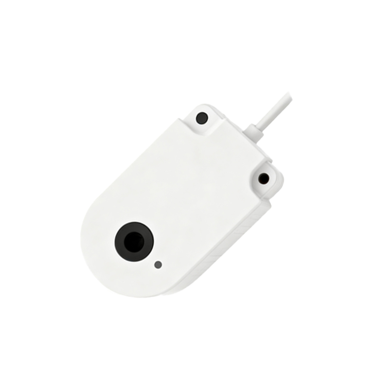
A typical setup involves the sensor, a power supply, and the PLC input module. Photoelectric sensors are generally categorized by their output type: NPN (sinking) or PNP (sourcing). This designation is crucial as it determines the current flow and compatibility with your PLC. Most PLC digital input modules are designed to accept either type, but their common point configuration (sinking or sourcing) must match. Always consult the datasheets of both the sensor and the PLC module before proceeding.
Standard Wiring Configurations
For a PNP (Sourcing) Sensor:
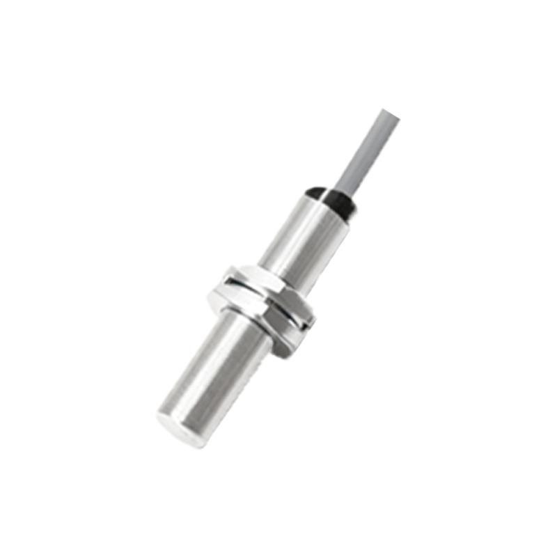
A PNP sensor switches the positive voltage to its output wire. In this configuration, the PLC input module's common terminal (COM) is connected to the 0V (DC negative) of the power supply. The wiring sequence is as follows:
1. Connect the sensor's brown wire (typically +V, e.g., 24V DC) to the positive terminal of the power supply.
2. Connect the sensor's blue wire (typically 0V) to the negative terminal of the power supply.
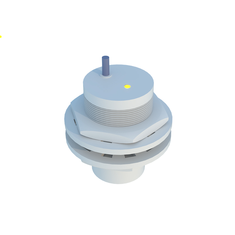
3. Connect the sensor's black wire (the switched output) to the designated PLC input terminal (e.g., I0.0).
4. Finally, connect the COM terminal of the PLC input module to the same negative (0V) terminal as the sensor's blue wire. When the sensor detects an object, it sources current from its brown wire, through its internal switch, out the black wire, into the PLC input, and down to the COM/0V, completing the circuit and signaling the PLC.
For an NPN (Sinking) Sensor:
An NPN sensor switches the negative or 0V path. Here, the PLC input module's common terminal (COM) must be connected to the positive voltage (e.g., +24V). The wiring is as follows:
1. Connect the sensor's brown wire to the positive terminal of the power supply.
2. Connect the sensor's blue wire to the negative terminal.
3. Connect the sensor's black wire (output) to the PLC input terminal.
4. Connect the COM terminal of the PLC input module to the same positive terminal as the sensor's brown wire. Upon detection, the NPN sensor completes the path to 0V, sinking current from the PLC input, through the black wire, and out the blue wire.
Critical Considerations for Reliable Operation
1. Shielded Cabling: Always use shielded cables for sensor connections, especially in environments with significant electromagnetic interference (EMI). Properly ground the cable shield at the control panel end only to drain noise.
2. Separate Power Supplies: For sensitive analog sensors or in complex systems, consider using a dedicated, regulated power supply for sensors separate from the PLC's power. This isolates noise from motor drives or other inductive loads.
3. Fusing and Protection: Incorporate a fast-acting fuse (e.g., 2A) in the positive supply line to the sensor circuit. For added protection, especially in dusty or wet environments, use a protective relay or an interface module between the sensor and the PLC to isolate the control logic from potential voltage spikes or wiring faults.
4. Correct Sourcing/Sinking Match: Mismatching an NPN sensor with a sourcing PLC input (or vice versa) will result in a non-functional circuit. Some modern PLC modules are switchable or universal, accepting both types by software configuration.
5. Diagnostic LEDs: Utilize the indicator LEDs on both the sensor and the PLC input module. A lit sensor LED with no corresponding PLC input activation is a clear indicator of a wiring fault or mismatch.
Advanced Connection: Analog and IO-Link Sensors
Modern photoelectric sensors often provide analog (4-20mA or 0-10V) or IO-Link digital communication outputs. For analog sensors, connect the output wires to an analog input module, ensuring a proper common ground reference. IO-Link sensors require a point-to-point connection to an IO-Link master module, which handles both power and bidirectional data communication, simplifying wiring and enabling advanced parameterization and diagnostics directly from the PLC software.
In conclusion, meticulous attention to the sensor's output type, proper common point connection at the PLC, and adherence to noise reduction and protection practices are the foundations of a robust photoelectric sensor-PLC interface.