Two-wire proximity sensors are fundamental components in modern industrial automation, offering a simplified and cost-effective solution for non-contact object detection. Unlike their three-wire counterparts, which require separate power, signal, and ground connections, two-wire sensors integrate directly into the load circuit. This article provides a detailed analysis of the typical wiring diagrams, operational principles, and key considerations for implementing these versatile devices.
The core principle of a two-wire AC or DC proximity sensor lies in its series connection with the load, such as a programmable logic controller (PLC) input module, a relay coil, or a contactor. In a standard wiring diagram, the two wires are designated as Brown (or Black) and Blue, following international color-coding conventions (IEC). The Brown wire is connected to the positive terminal of the DC supply or the live (L) terminal of an AC supply. The Blue wire is then connected to one terminal of the load. The other terminal of the load completes the circuit by connecting to the negative (DC) or neutral (AC) side of the power supply.
When no target is within the sensor's detection range, a small leakage current, typically in the range of 1-2 mA, flows through the sensor. This current is insufficient to activate the connected load, keeping it in the "OFF" state. Upon detecting a valid target, the sensor's internal solid-state switch (often a MOSFET or a TRIAC) closes. This action significantly reduces the sensor's internal impedance, allowing the full operating current to flow through the circuit, thereby energizing the load and switching it to the "ON" state. The simplicity of this "switch closed = target present" logic is a key advantage.
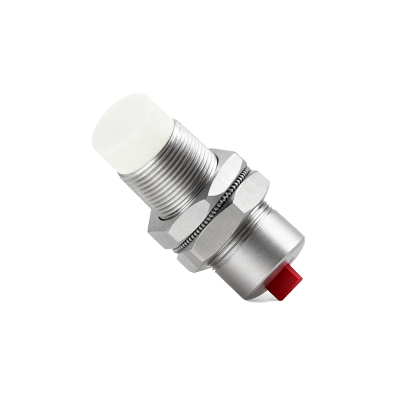
Examining the circuit diagram reveals critical electrical characteristics. The sensor itself has a voltage drop, known as the residual voltage or on-state voltage drop (V_d). When active, this voltage, usually between 1.5V to 5V depending on the model and current, appears across the sensor's terminals. This voltage is lost from the supply available to the load. Therefore, it is crucial to ensure that the load's minimum operating voltage is met even with this drop. For instance, a 24V DC sensor with a 3V drop supplies only 21V to the load. Most PLC inputs are designed to accept this, but it must be verified.
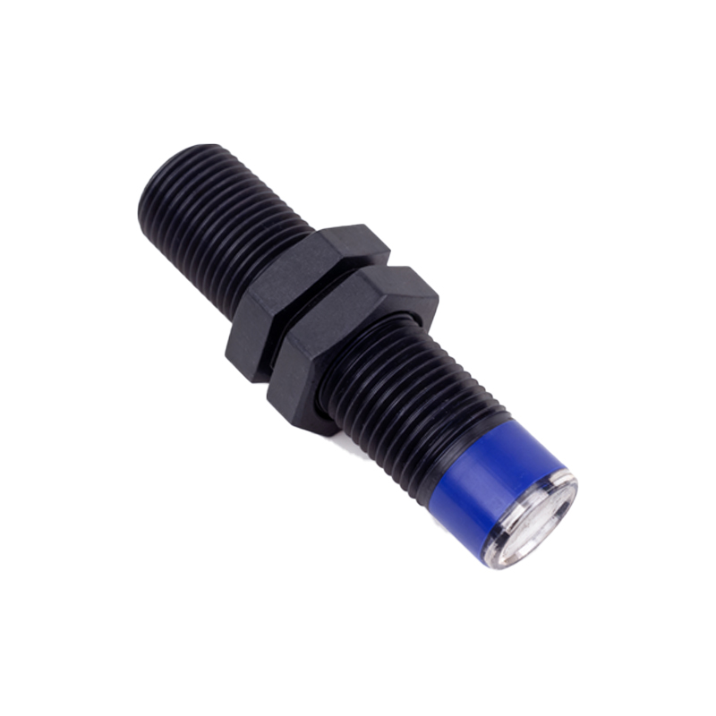
Another vital parameter is the off-state leakage current. Although small, this continuous current can cause issues with highly sensitive loads or certain PLC input modules, potentially leading to false triggering. Many modern PLCs have a high input impedance and a defined threshold to ignore this leakage. If necessary, a bleeder resistor can be wired in parallel with the load to shunt the leakage current away.
For AC two-wire sensors, the wiring diagram is similar, but the internal switching component is a TRIAC. A crucial consideration here is the inrush current of the load, especially inductive loads like relay coils. The sensor's datasheet specifies a maximum permissible inrush current. Exceeding this value can weld the internal TRIAC contacts shut, causing a permanent failure. To mitigate this, protective circuits like RC snubbers or metal-oxide varistors (MOVs) are sometimes integrated or recommended for parallel connection with the load.
When designing a control panel, proper fusing is mandatory. A fast-acting fuse should be placed on the supply line to protect the sensor and wiring from short-circuit faults. The sensor's datasheet provides the maximum steady-state current rating. The selected fuse rating should be slightly above the expected operating current but below the sensor's absolute maximum rating. Grounding the sensor's metal housing, if applicable, is also essential for electrical safety and noise immunity, especially in environments with variable frequency drives or welding equipment.
Troubleshooting often involves a multimeter. Common issues include no output when a target is present. This can be caused by an incorrect power supply voltage, a load with too high an impedance (or too low a current draw), or a damaged sensor. Measuring the voltage across the sensor's terminals with and without a target is a standard diagnostic step. A high voltage drop (close to the supply voltage) when a target is present indicates the internal switch is not closing, suggesting sensor failure. Conversely, a very low voltage drop without a target suggests a shorted internal switch.
In summary, the two-wire proximity sensor circuit diagram represents an elegant and efficient design for industrial sensing. Successful implementation requires careful attention to the electrical compatibility between the sensor's characteristics—residual voltage, leakage current, and current ratings—and the connected load. By adhering to the wiring diagrams and specifications provided by manufacturers, engineers can ensure reliable, maintenance-free operation in diverse automation applications, from packaging machinery to automotive assembly lines.