Proximity sensors are critical components in industrial automation, enabling non-contact detection of objects with high precision. Proper setup and calibration are essential to ensure reliable operation and longevity. This guide provides a step-by-step illustrated approach to configuring and troubleshooting common proximity sensor types, including inductive, capacitive, and ultrasonic sensors.
Step 1: Pre-Installation Checks
Before mounting the sensor, verify its specifications match the application requirements. Check the sensing range, output type (NPN/PNP, NO/NC), and supply voltage. Inspect the sensor housing for damage and ensure the sensing face is clean. For inductive sensors, confirm the target material is detectable (e.g., metals for inductive types). Capacitive sensors require consideration of the dielectric constant of the target material.
Step 2: Mounting and Alignment
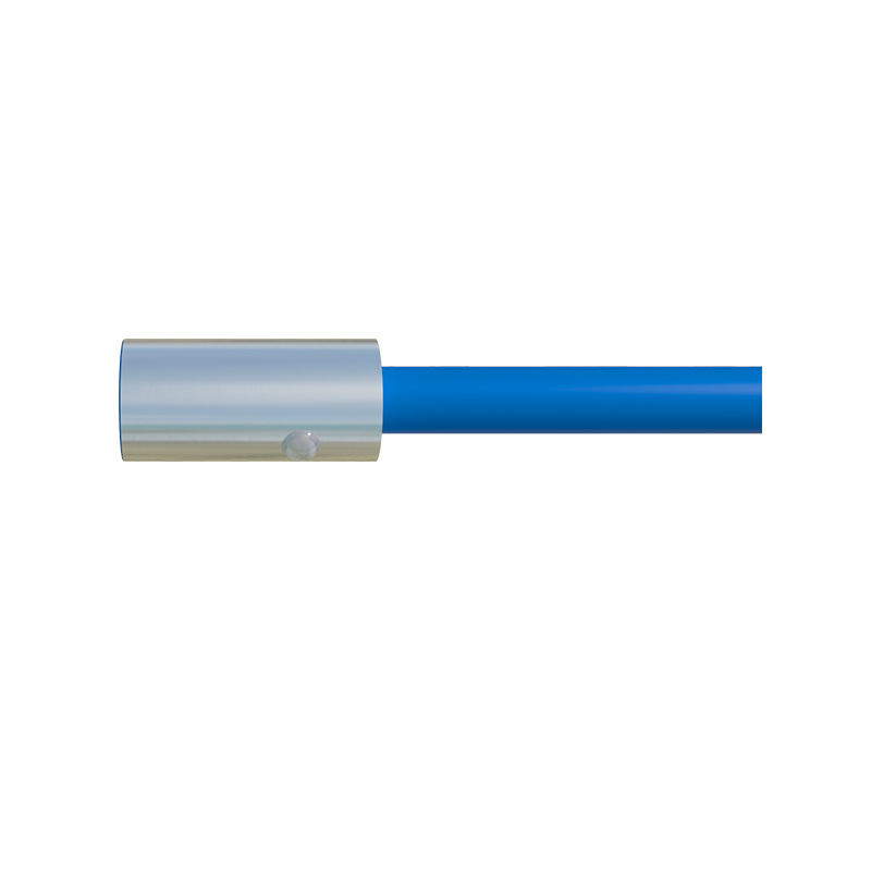
Mount the sensor securely using appropriate brackets, ensuring minimal vibration or misalignment. Maintain the recommended gap between the sensor and target—typically 0.8 times the rated sensing distance for inductive sensors. Avoid mounting near metal surfaces or other sensors that could cause interference. For cylindrical sensors, use alignment tools to parallelize the sensing face with the target surface.
Step 3: Wiring and Power Connection
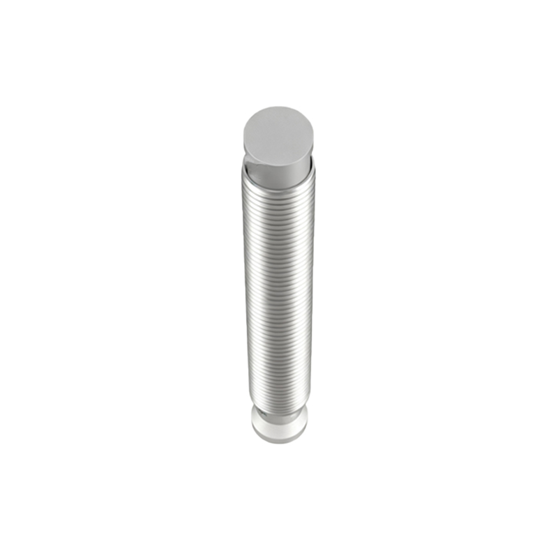
Connect the sensor to the power supply according to the wiring diagram. For DC sensors, observe polarity: brown wire to positive (+), blue wire to negative (-). The black wire is typically the output signal. Use shielded cables in electrically noisy environments and ground the shield at one end. After wiring, apply power and check the indicator LED. A steady or blinking LED usually indicates normal operation.
Step 4: Sensitivity Adjustment
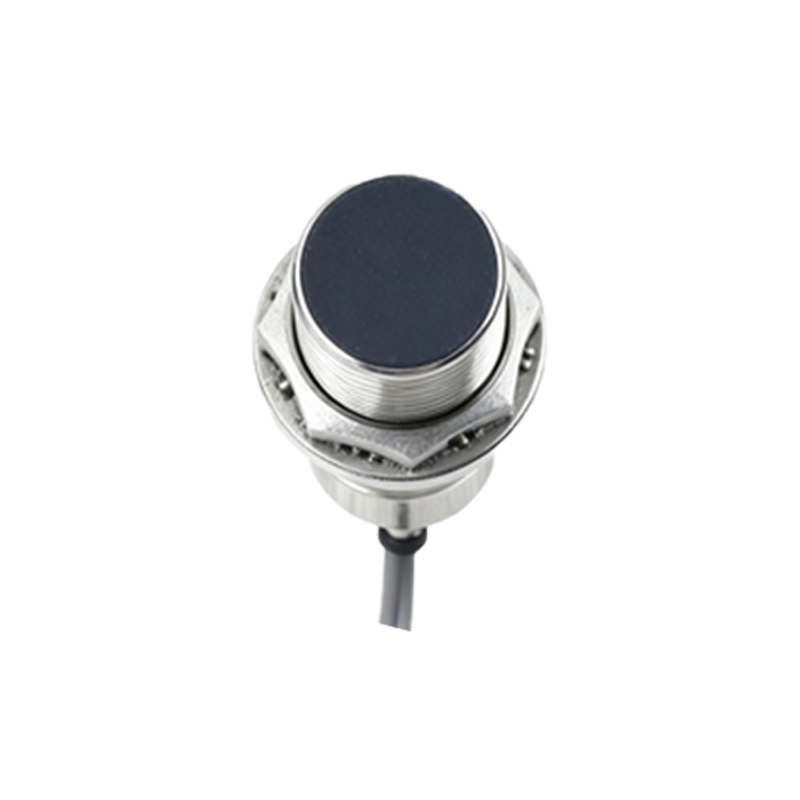
Most proximity sensors feature a potentiometer or teach-in button for sensitivity calibration. For adjustable models, use a non-metallic screwdriver to turn the potentiometer. Start with minimum sensitivity and gradually increase until the sensor reliably detects the target at the required distance. For teach-in sensors, place the target at the desired sensing point and press the teach button until the LED confirms calibration.
Step 5: Testing and Validation
Move the target object through the sensing range at operational speeds. Verify the sensor triggers consistently without false positives. Use a multimeter to measure output voltage/current under load. For critical applications, test with temperature variations and environmental factors like humidity or dust. Document the final settings for future reference.
Step 6: Troubleshooting Common Issues
If the sensor fails to detect, check power supply stability and wiring connections. Ensure the target is within range and properly aligned. For erratic behavior, inspect for external interference from motors or frequency converters. Reduce sensitivity if the sensor is triggered by background objects. Clean the sensing face regularly to prevent contamination buildup.
Illustrated Diagrams:
Diagram A shows correct vs. incorrect mounting angles, highlighting the importance of parallel alignment. Diagram B depicts wiring configurations for 2-wire, 3-wire, and 4-wire sensors. Diagram C illustrates sensitivity adjustment zones, demonstrating how to avoid over-ranging. Diagram D provides a flowchart for systematic troubleshooting.
Regular maintenance, including periodic recalibration and environmental checks, will optimize sensor performance. Always refer to the manufacturer’s manual for model-specific instructions.