Proximity sensors are critical components in modern industrial automation, providing non-contact detection of metallic and non-metallic objects. Proper installation and calibration are essential for ensuring reliable operation, minimizing downtime, and extending sensor lifespan. This guide outlines best practices for engineers and technicians.
Installation begins with selecting the correct sensor type—inductive, capacitive, or ultrasonic—based on the target material and environmental conditions. Mounting location is paramount; ensure the sensor is positioned to avoid physical damage from moving parts, excessive vibration, or incidental contact. For inductive sensors, maintain a clean mounting surface free of metallic debris to prevent false triggering. The sensing face must be aligned parallel to the target surface, with the recommended sensing distance (typically 0.8 to 1.2 times the nominal sensing range) carefully maintained. Avoid mounting multiple sensors in close proximity without adequate shielding, as mutual interference can cause erratic behavior.
Wiring must adhere to manufacturer specifications and relevant electrical codes. Use shielded cables in electrically noisy environments, grounding the shield at the controller end only to prevent ground loops. Ensure power supply voltage matches the sensor rating, and incorporate surge protection if installed near high-power equipment like motors or solenoids. For DC sensors, observe correct polarity; reverse connection can permanently damage the internal circuitry. Always disconnect power during wiring to prevent short circuits.
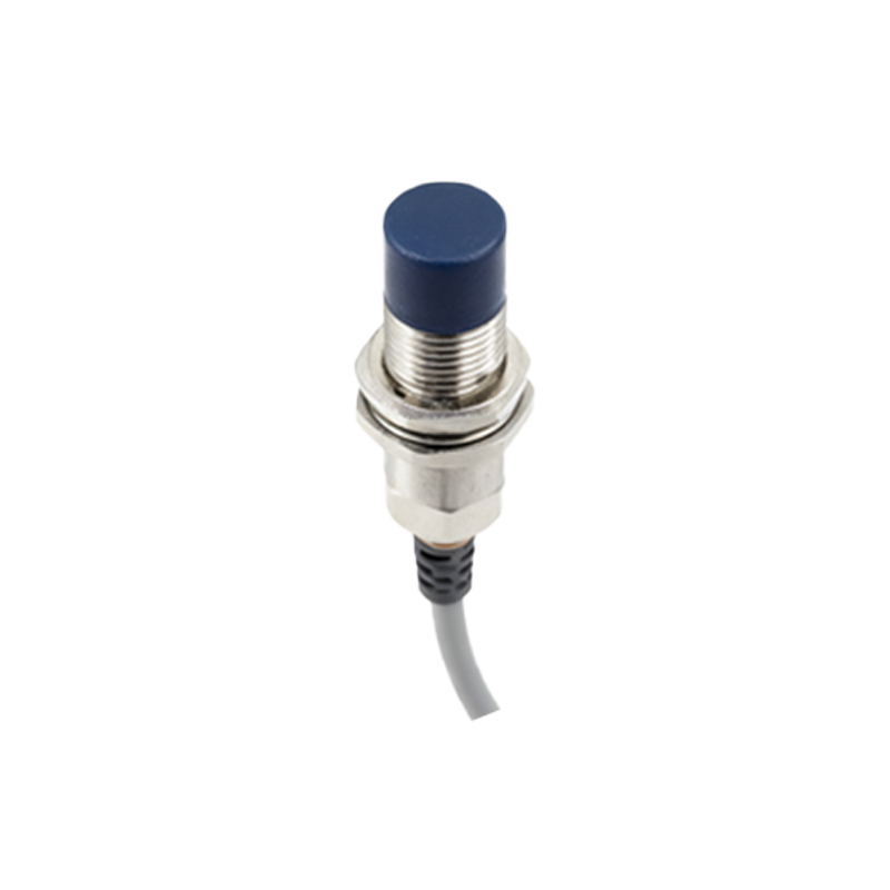
Calibration, or tuning, adjusts the sensor to its specific application. After installation, power the system and introduce the target object. Use the sensor’s potentiometer (if available) or teach-in function to set the sensing threshold. For adjustable-range sensors, fine-tune the sensitivity so the sensor reliably detects the target at the desired distance while ignoring background objects. In applications with varying target sizes or materials, set a hysteresis band to prevent chattering—rapid on/off switching near the detection threshold. Test the sensor across expected operating temperatures and conditions, as thermal drift can affect performance.
Diagnostic LEDs simplify troubleshooting. A steady LED indicates target detection, while a flashing pattern often signals issues like overload, short circuit, or contamination. Regularly inspect the sensing face for buildup of dust, oil, or coolant, which can attenuate the sensing field. For harsh environments, consider sensors with IP67 or higher ratings, and use protective housings if exposed to chemicals or mechanical abrasion.
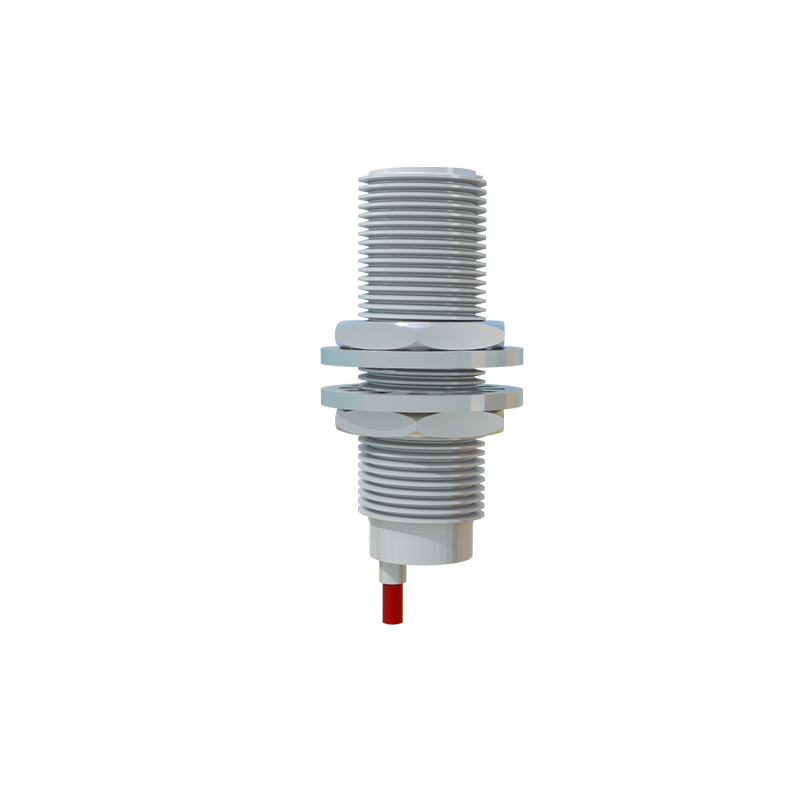
Long-term maintenance involves periodic verification of sensing distance and output stability. Keep a log of calibration settings for quick restoration after sensor replacement. By following these installation and calibration protocols, engineers can optimize system performance, enhance safety, and reduce maintenance costs in automated production lines, material handling, and robotic systems.