Proximity sensors are essential components in industrial automation, offering non-contact detection of metallic or non-metallic objects. Proper assembly ensures optimal performance, longevity, and safety. This guide provides a step-by-step diagram-based approach to assembling proximity sensors, tailored for engineers and technicians in the electrical and automation sectors.
Step 1: Preparation and Safety
Before assembly, gather all necessary tools and components: the proximity sensor unit, mounting bracket, connector, wiring cables, and a torque wrench. Ensure the power supply is disconnected to prevent electrical hazards. Wear appropriate personal protective equipment (PPE), such as insulated gloves and safety glasses. Verify the sensor model matches the application requirements, including sensing range, output type (PNP/NPN), and voltage rating.
Step 2: Mounting the Sensor
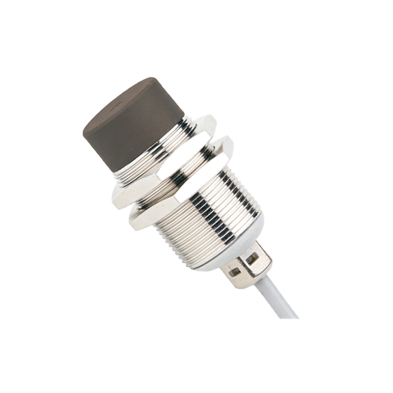
Refer to the assembly diagram (Fig. 1) for mounting details. Position the sensor in the designated location, typically on a stable surface near the target object. Use the provided mounting bracket to secure the sensor, ensuring it is aligned parallel to the detection area. Tighten the mounting screws with a torque wrench to the specified value (e.g., 0.5-0.8 N·m) to avoid over-tightening, which can damage the housing. Maintain a clearance of at least two times the sensor’s diameter from surrounding metal objects to prevent interference.
Step 3: Electrical Connections
Consult the wiring diagram (Fig. 2) for correct terminal connections. Most proximity sensors have three wires: brown (power supply +), blue (power supply -), and black (output signal). Strip the wire ends to the recommended length (usually 7-10 mm). Insert the wires into the connector terminals according to the color coding, ensuring no loose strands are exposed. Secure the connections by tightening the terminal screws to the manufacturer’s torque specification. For waterproof models, apply sealing gaskets and ensure the connector is fully seated to maintain IP rating integrity.
Step 4: Calibration and Testing
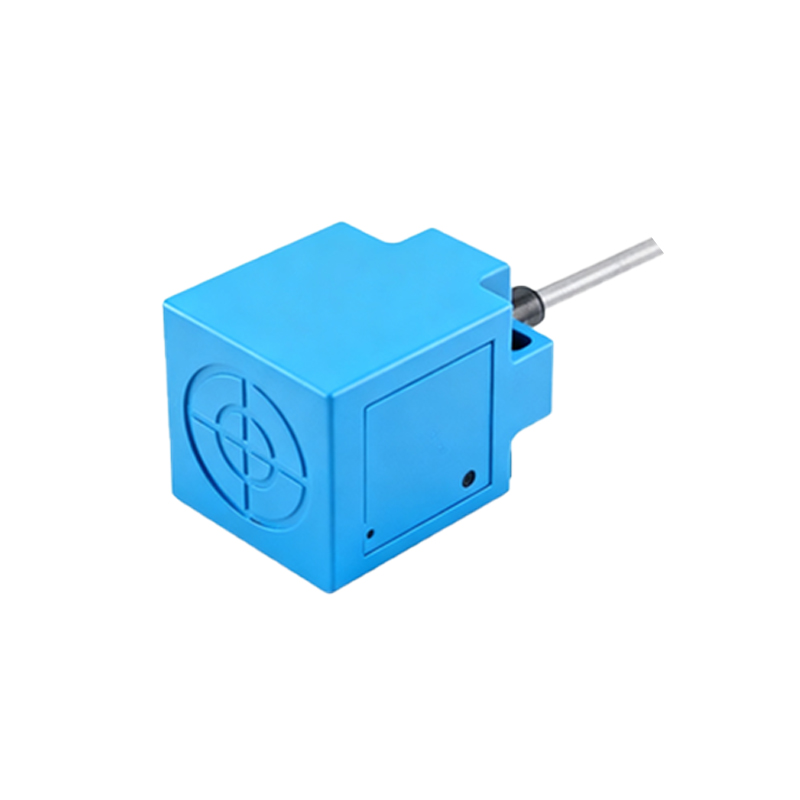
After assembly, power on the system and perform calibration. Adjust the sensor’s sensing distance using the potentiometer (if available) to match the target object’s size and material. Test the sensor by moving a target object within its range; the output indicator LED should activate upon detection. Use a multimeter to verify the output voltage or current signals align with datasheet specifications. For inductive sensors, ensure the target is within the nominal sensing range (e.g., 2-10 mm for standard models) and avoid excessive vibration or temperature extremes.
Step 5: Final Inspection and Maintenance
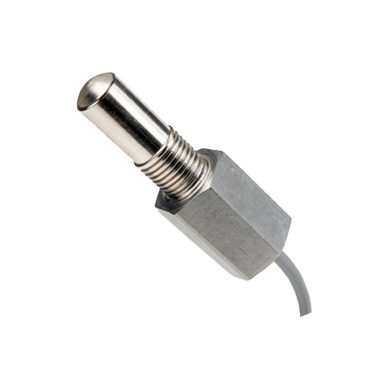
Conduct a final inspection to check for loose connections, proper alignment, and environmental factors like dust or moisture. Document the assembly process and settings for future reference. Regular maintenance includes cleaning the sensor face with a soft cloth, checking for wear or corrosion, and recalibrating periodically to ensure consistent performance. Avoid using harsh chemicals that could degrade the sensor housing.
Common Assembly Errors and Solutions:
- Error: Sensor fails to detect objects. Solution: Verify wiring polarity and ensure the target material is compatible (e.g., ferrous metals for inductive sensors).
- Error: False triggering. Solution: Increase clearance from adjacent metal surfaces or adjust sensitivity settings.
- Error: Overheating. Solution: Check voltage ratings and ensure adequate ventilation around the sensor.
By following this diagram-based guide, engineers can achieve reliable proximity sensor assembly, enhancing system efficiency in applications like conveyor systems, robotic arms, and safety interlocks. Always refer to the manufacturer’s manual for model-specific details, as designs may vary by brand and type (e.g., capacitive, ultrasonic). Proper assembly not only extends sensor life but also reduces downtime in industrial operations.