Proximity sensors are indispensable components in modern industrial automation, manufacturing lines, and safety systems. They detect the presence or absence of an object without physical contact, relying on electromagnetic fields, infrared light, or ultrasonic sound. When a proximity sensor malfunctions, it can lead to production downtime, safety hazards, and costly repairs. This guide provides a systematic approach for engineers and technicians to diagnose and resolve common proximity sensor failures.
Step 1: Initial Symptom Assessment and Safety
Before any hands-on work, conduct a thorough operational assessment. Document the specific symptoms: Is the sensor failing to detect any object (false negative), constantly indicating presence (false positive), or providing intermittent signals? Simultaneously, ensure all safety protocols are followed. De-energize and lock out the relevant electrical circuit (LOTO procedure) before inspection. Verify that the machinery is in a safe state for maintenance.
Step 2: Visual and Physical Inspection
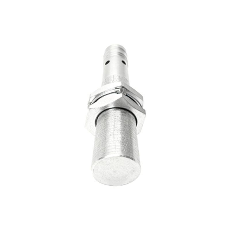
Begin with a comprehensive visual check.
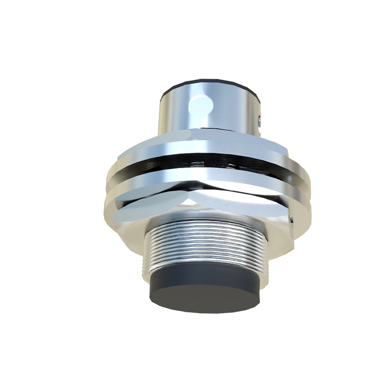
Sensor Body: Look for cracks, dents, or signs of impact. Physical damage can misalign internal components or break seals.
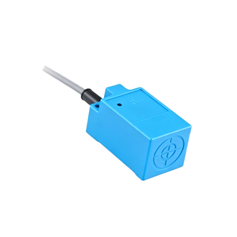
Sensing Face: Clean the active sensing surface. Accumulation of metal shavings, oil, dust, or other contaminants can severely attenuate the sensor's field or beam. Use appropriate, non-abrasive cleaners.
Mounting: Check for loose mounting hardware or brackets. Vibration can cause the sensor to shift, altering its detection range or target alignment. Ensure the sensor is securely fastened and correctly positioned relative to the target object.
Wiring and Connections: Inspect the cable for cuts, pinch points, or insulation damage. Examine the connector for corrosion, bent pins, or looseness. A poor connection is a leading cause of intermittent faults.
Step 3: Electrical and Environmental Verification
Power Supply: Using a multimeter, verify that the sensor is receiving the correct voltage (e.g., 10-30V DC for many inductive sensors) at its terminals. Check for voltage drops under load. Unstable or incorrect power is a common root cause.
Load Check: Ensure the sensor's output is connected to a load (e.g., PLC input, relay coil) within its specified current and voltage ratings. An overloaded or short-circuited output can damage the sensor's internal switching element.
Environmental Factors: Confirm the operating environment is within the sensor's specifications. Key factors include:
Temperature: Extreme heat or cold can affect electronic components and sensing distance.
EMI/RFI: Strong electromagnetic or radio frequency interference from nearby motors, welders, or variable frequency drives (VFDs) can disrupt sensor operation. Check cable routing and consider using shielded cables grounded at one end.
Material Compatibility: For inductive sensors, ensure the target material is detectable (ferrous metals are standard). The sensor's rated sensing distance is typically for mild steel; other materials have reduction factors. For capacitive sensors, changes in the target material's dielectric constant can affect performance.
Step 4: Target Object Analysis
The problem may not be the sensor itself but the target.
Size and Shape: The target must be large enough to reliably interrupt the sensor's field. A small or narrow target might not be consistently detected.
Approach Direction: For optimal performance, the target should approach the sensor's sensing face directly, not at a steep angle.
Material Changes: A switch from a steel to an aluminum target, for instance, will require recalibration or a different sensor type for inductive models.
Step 5: Functional Testing and Calibration
Bench Test: If possible, isolate the sensor. Apply the correct voltage in a controlled environment and use a known-good target to test its response. This confirms if the sensor is functional independently of the machine wiring.
Output Monitoring: Use an oscilloscope or a PLC diagnostic tool to monitor the sensor's output signal. Look for a clean, sharp transition without noise or chatter when the target enters and leaves the sensing field.
Sensing Distance Check: Over time, sensors can experience "drift," where the effective sensing distance decreases. Test the actual sensing distance against the datasheet specification. Do not attempt to adjust potentiometers (if present) beyond their specified range.
Step 6: Advanced Diagnostics and Replacement
If all previous steps fail to identify the issue:
Swap Test: Replace the suspect sensor with a known-working unit of the same model. If the problem resolves, the original sensor is faulty. This is often the quickest diagnostic step in a well-stocked maintenance department.
Internal Failure: Common internal failures include damaged oscillator circuits (in inductive sensors