Proximity sensors are indispensable components in modern industrial automation, and the S8 series stands out for its reliability, precision, and versatility. Proper setup of an S8 proximity sensor is crucial to ensure optimal performance in applications ranging from object detection and positioning to counting and safety systems. This guide provides a step-by-step approach to configuring an S8 proximity sensor, adhering to industry best practices.
Before beginning the installation, ensure the work area is de-energized and locked out to prevent electrical hazards. Gather the necessary tools: the S8 sensor, appropriate mounting hardware, a power supply matching the sensor's specifications (typically 10-30V DC for most models), and the connected control device (e.g., a PLC). Always consult the manufacturer's datasheet for your specific S8 model, as specifications can vary.
The first step is mechanical mounting. S8 sensors are available in tubular or rectangular housings. Select a stable location free from excessive vibration and within the specified sensing range. Ensure the target object material (metal, plastic, etc.) is compatible with the sensor's detection principle—inductive sensors detect metals, while capacitive versions handle non-metals. Align the sensor face perpendicular to the target's approach path. For tubular sensors, use the provided locknuts to secure the unit, avoiding over-tightening to prevent housing damage. Maintain a clearance of at least one sensor diameter from surrounding metal objects to avoid false triggers.
Wiring is the next critical phase. S8 sensors typically have three wires: brown (power +), blue (power -), and black (output). For a 3-wire DC model, connect the brown wire to the positive DC supply terminal and the blue wire to the negative terminal. The black output wire connects to the PLC input or load. For 4-wire models, which include both PNP (sourcing) and NPN (sinking) outputs, verify your system's requirement. PNP outputs switch the positive voltage to the load, common in Europe, while NPN switches the negative, often used in Asia. Double-check polarity; incorrect connections can permanently damage the sensor. Use shielded cables in electrically noisy environments, grounding the shield at the control panel end only.
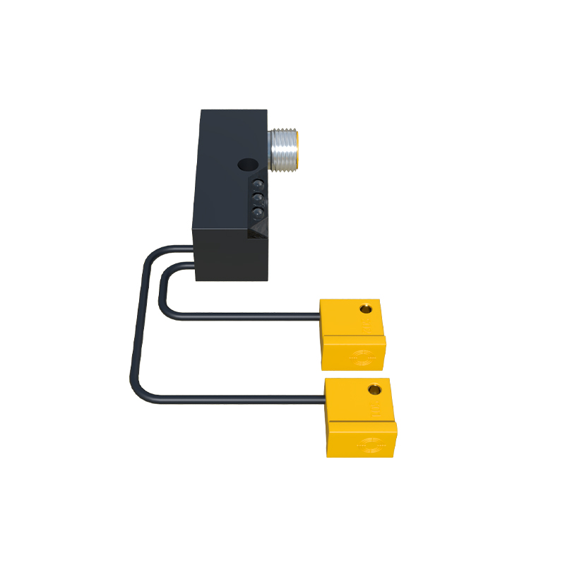
After securing connections, apply power. Most S8 sensors feature an LED indicator that illuminates when power is present and blinks or changes color upon target detection. This LED is vital for initial setup. Adjust the sensor's position so the target enters the sensing field reliably. The effective sensing distance (Sn) is specified in the datasheet. Note that for inductive sensors, the reduction factor for different metals (e.g., steel, aluminum, copper) must be considered—the actual sensing distance may be less for non-ferrous metals.
Fine-tuning involves setting sensitivity and response time, if the S8 model includes potentiometers or DIP switches. A sensitivity adjustment allows compensation for target size or material variations. Turn the potentiometer clockwise to increase sensitivity (longer range) or counterclockwise to decrease it, minimizing interference from background objects. The response time adjustment defines how quickly the output reacts to a target's presence or absence. In high-speed applications, set a faster response, but beware of potential signal chatter. For models with teach-in functionality, follow the manual's procedure: present the target at the desired detection point and activate the teach-in button to store the threshold.
Testing under actual operating conditions is mandatory. Cycle the target object repeatedly at the maximum expected speed. Monitor the output with a multimeter or PLC software to ensure consistent switching without missed detections or false signals. Check for environmental factors like temperature extremes, dust, moisture, or coolant splashes. S8 sensors are often rated IP67, meaning they are dust-tight and can withstand temporary immersion, but verify the rating suits your environment.
Finally, document the setup parameters, including mounting distance, sensitivity setting, and wiring diagram. Regular maintenance checks should include cleaning the sensor face from debris and verifying the mounting integrity. By meticulously following these steps, engineers can ensure the S8 proximity sensor delivers long-term, reliable service, enhancing the efficiency and safety of automated systems. Remember, when in doubt, always prioritize the guidelines provided in the official S8 technical manual.