Metal proximity sensors are integral components in modern industrial automation, serving as non-contact detection devices that identify the presence or absence of metallic objects within their sensing range. These sensors operate based on electromagnetic principles, primarily utilizing inductive technology to detect ferrous and non-ferrous metals without physical contact. This capability makes them ideal for harsh environments where durability, reliability, and precision are paramount, such as in manufacturing assembly lines, robotic systems, and safety interlocks.
The core function of a metal proximity sensor is to generate an output signal when a metal target enters its detection zone. This output can be in the form of a digital switch signal (e.g., NPN or PNP transistor outputs) or an analog signal proportional to the distance of the target. Common applications include object counting, position sensing, limit switching, and material handling control. For instance, in conveyor systems, these sensors ensure proper alignment of metal parts, while in automotive production, they monitor the presence of components during assembly processes, enhancing efficiency and reducing downtime.
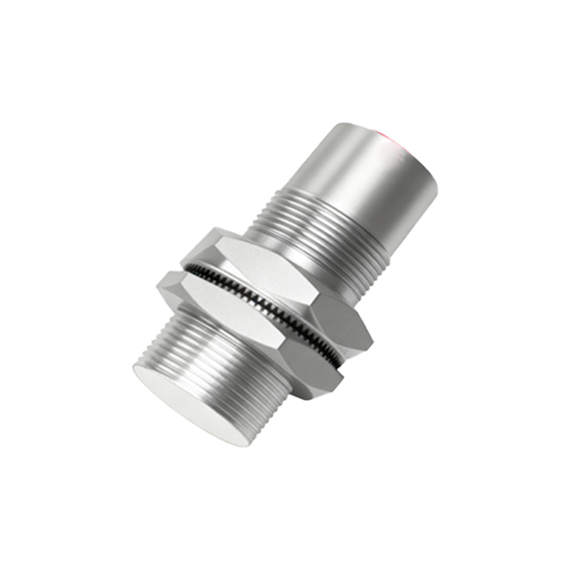
The schematic principle of an inductive metal proximity sensor revolves around an oscillator circuit, a detection coil, and a signal processing unit. At the heart of the sensor is an LC oscillator that generates a high-frequency electromagnetic field through the coil. When a metal object approaches this field, eddy currents are induced on the surface of the metal, causing a change in the oscillator's amplitude or frequency. This alteration is detected by the sensor's circuitry, which then triggers an output state change. The schematic typically includes components such as a power supply input (often 10-30V DC), the oscillator with a resonant coil, a demodulator to convert the signal, and an output driver stage. For example, a standard NPN output schematic shows the sensor connecting to a load (like a PLC input) with the output transistor sinking current to ground when activated.
Key design considerations in the schematic involve the sensing distance, which depends on factors like coil size, metal type, and oscillator frequency. Ferrous metals (e.g., iron) generally yield longer detection ranges due to their magnetic permeability, while non-ferrous metals (e.g., aluminum) may require adjusted sensitivity. Additionally, environmental factors such as temperature fluctuations and electromagnetic interference are mitigated through shielding and robust circuit design. Modern sensors often incorporate integrated circuits for enhanced stability, with schematics including protection diodes against reverse polarity and voltage spikes.
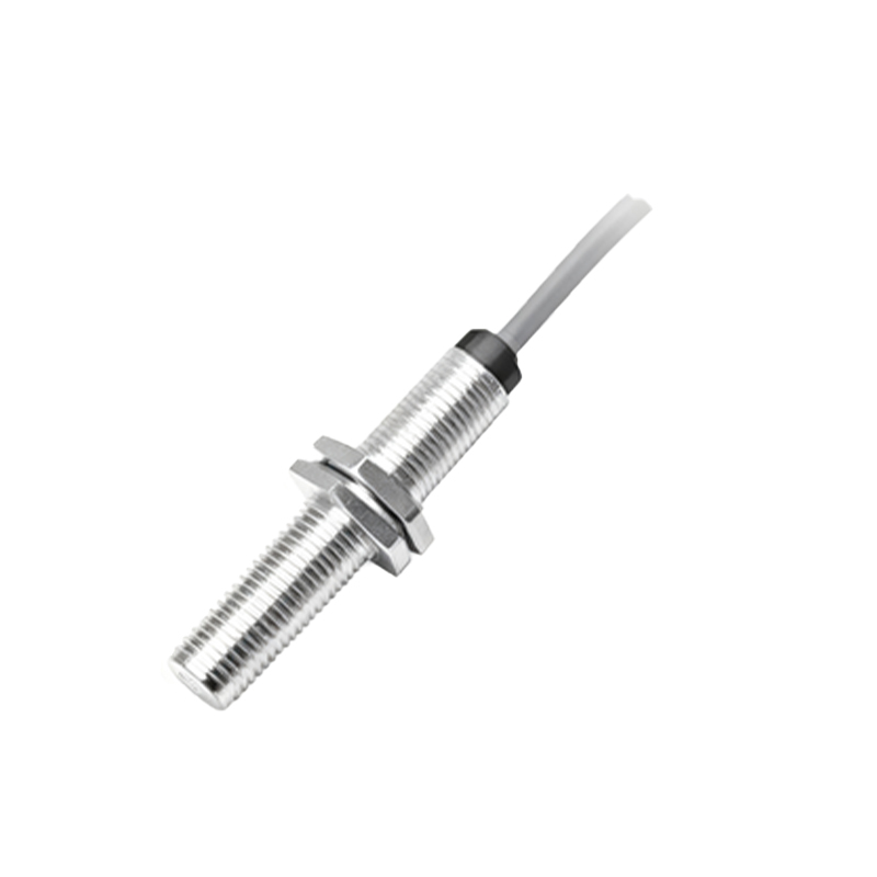
In practice, interpreting a metal proximity sensor schematic involves understanding the wiring connections: brown wire for positive supply, blue for negative or ground, and black for the output signal. The schematic may also depict diagnostic LEDs for status indication. By analyzing these diagrams, engineers can troubleshoot issues, optimize placement, and integrate sensors into larger control systems. As Industry 4.0 advances, metal proximity sensors continue to evolve with features like IO-Link communication, enabling real-time data exchange for predictive maintenance and smart factory applications. Overall, mastering their functions and schematic principles is essential for leveraging automation benefits, ensuring operational safety, and driving industrial innovation.