In the realm of industrial automation and control systems, proximity sensors stand as fundamental components for non-contact object detection. A nuanced and often discussed operational characteristic is the observed phenomenon where, as a target object moves closer to the active sensing face of the sensor, the output current signal can, in specific configurations, exhibit a decrease. This inverse relationship between proximity and current may seem counterintuitive at first glance, but it is rooted in the underlying physics and the design principles of certain sensor types, particularly inductive and capacitive variants.
To comprehend this behavior, one must first distinguish between the primary operating modes. Many modern proximity sensors provide a digital ON/OFF (switch) output, where the current is either fully on (saturated at the rated load current) or completely off. In this binary mode, the concept of "current decreasing with proximity" does not apply within the sensing range; the switch simply changes state at a defined point. The phenomenon in question is more relevant to analog output sensors or can be inferred from the internal oscillator circuit behavior in switching sensors during the approach prior to the switch point.
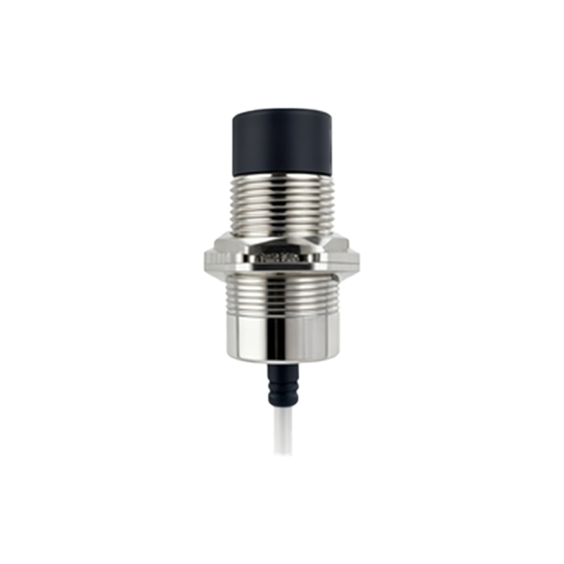
Consider a standard inductive proximity sensor. Its core consists of an oscillator circuit that generates a high-frequency electromagnetic field at the sensing face. When a metallic target enters this field, eddy currents are induced on the target's surface. These eddy currents draw energy from the oscillator, causing a damping or attenuation of the oscillation amplitude. The sensor's evaluation circuit monitors this amplitude. In a common design for a switching sensor, when the damping reaches a preset threshold (the switching point), the output transistor switches state. However, if we examine the current consumption of the oscillator circuit itself or the signal in an analog current output version (e.g., 4-20mA), the relationship becomes clear. The energy loss due to eddy currents increases as the target gets closer, requiring more power from the oscillator to maintain oscillation. Yet, in an analog output sensor configured for inverse response, the control circuit is designed to reduce its output current (e.g., move from 20mA towards 4mA) as the damping signal increases, effectively providing a signal that is inversely proportional to distance. This is a programmed response, not a direct electrical inevitability.
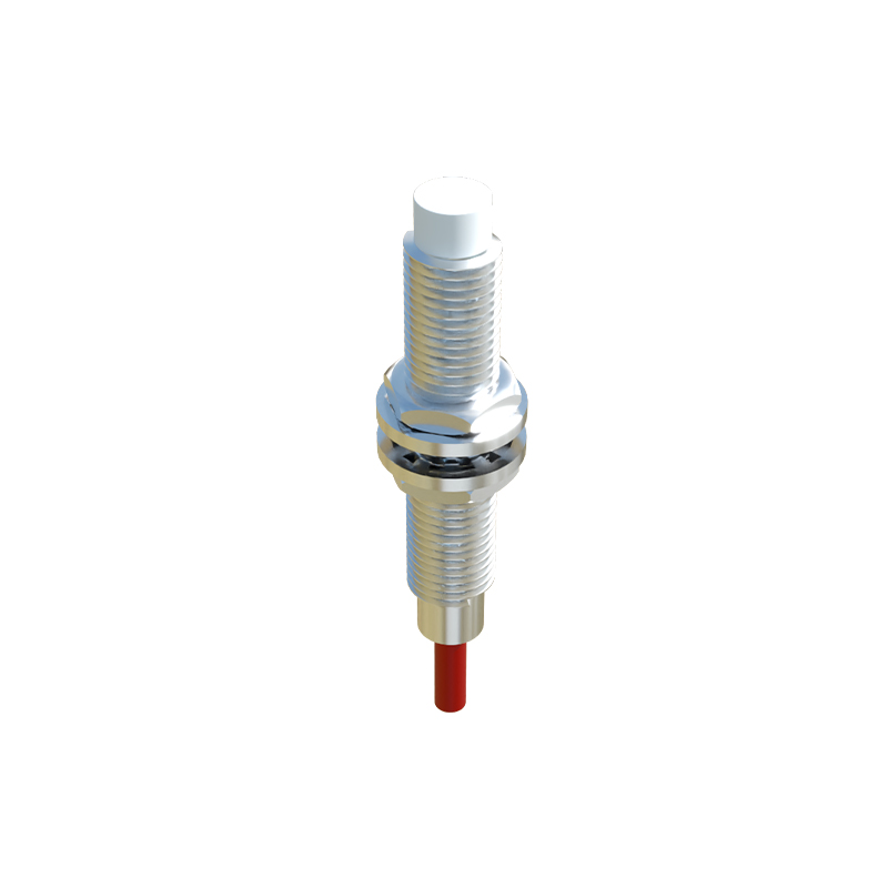
Similarly, for capacitive proximity sensors, which detect both metallic and non-metallic materials by measuring changes in capacitance, the principle can be mirrored. As an object approaches, the capacitance between the sensor's electrode and the target increases. The sensor's circuit converts this capacitance change into a signal. An analog output can be scaled so that increasing capacitance (decreasing distance) results in a decreasing output current, if such a scaling is required by the application. For instance, in a tank level sensing application where a full tank means the material is close to the sensor, a user might want 4mA to represent "full" and 20mA to represent "empty" for safety or intuitive reasons. The sensor electronics are calibrated to provide this inverse characteristic.
The primary technical rationale for employing an inverse current output lies in application-specific logic and fail-safe design. In process control, a "live zero" standard like 4-20mA is used because 0mA clearly indicates a wire break or power failure. Within this range, the scaling direction is flexible. An inverse output can be crucial for fail-safe conditions. If a critical process requires a valve to close (requiring minimum signal) when an object gets too close, an inversely scaled sensor directly provides that command signal. It eliminates the need for an additional inverter module in the control logic, simplifying system architecture and enhancing reliability.
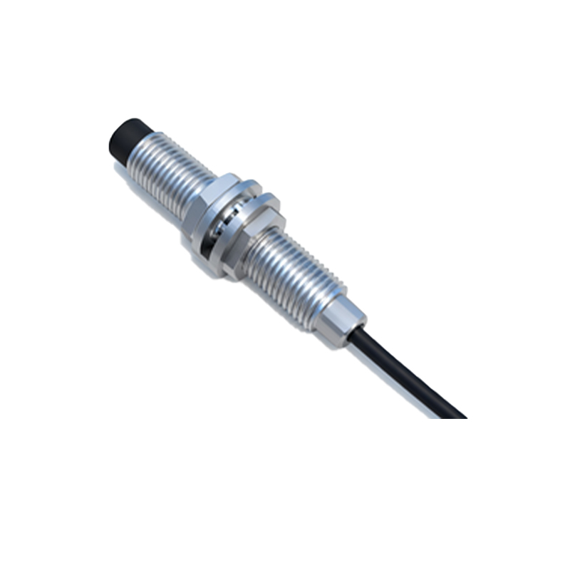
Furthermore, examining the internal diagnostics of a digital switching sensor reveals a related concept. The "switching hysteresis"—the difference between the switch-on and switch-off points—ensures stable operation. As a target approaches very slowly, the internal damping gradually increases. Right at the brink of the switching threshold, the sensor is in a high-gain state. While the output is still off, the power supply current draw might show a slight, non-linear variation due to the oscillator working harder against the damping, but this is a minor effect and not the primary "output current" discussed for analog systems.
In practical engineering, selecting a sensor with Normal (NO) or Inverse (NC) output characteristics is a deliberate choice. The terminology often refers to the switching logic of the output transistor (PNP vs. NPN sourcing configurations can also be described as "dark-on" or "light-on"). For analog sensors, the data sheet will explicitly define the transfer function: whether the output current increases (positive slope) or decreases (negative slope) with decreasing distance to the target. Misinterpretation of this specification can lead to incorrect wiring and dangerous control actions.
Therefore, the observation that "proximity sensor current gets smaller as the target gets closer" is an accurate description