In industrial automation, robotics, and countless electronic devices, proximity sensors play a critical role in detecting the presence or absence of an object without physical contact. A fundamental, yet often overlooked, parameter governing their reliable operation is the reset distance. Understanding this concept is essential for proper sensor selection, installation, and troubleshooting.
What is Reset Distance?
The reset distance, sometimes referred to as the release point or drop-out point, is the specific distance at which a proximity sensor changes its output state from "active" (e.g., ON, logic 1) back to "inactive" (e.g., OFF, logic 0) as the target object moves away from the sensor face. It is the counterpart to the operating point or switch-on distance, which is the distance at which the sensor activates as the target approaches.
Crucially, the reset distance is not equal to the operating point. Due to internal hysteresis designed into most sensors, the reset distance is typically shorter than the operating point. This hysteresis gap is intentional and vital.
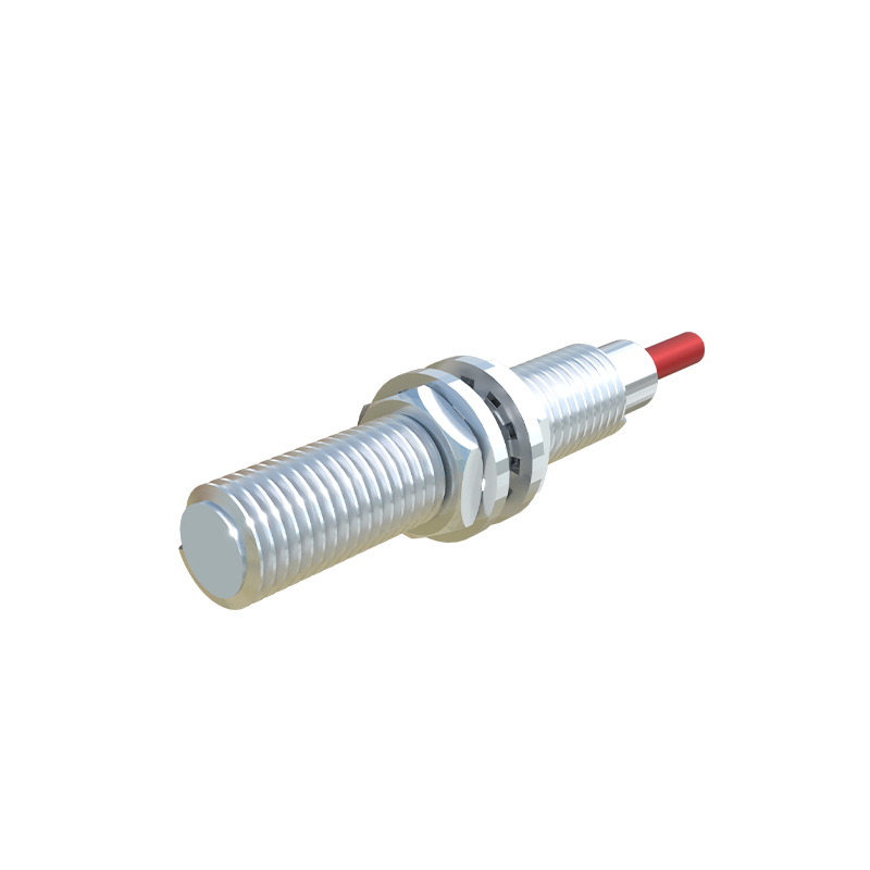
The Critical Role of Hysteresis
Hysteresis is the difference between the operating point and the reset point. Imagine a sensor with an operating point of 10mm and a reset point of 9mm. The hysteresis is 1mm. This design feature prevents "chattering" or rapid, unstable switching of the output when the target object is positioned precisely at the sensor's detection threshold. Without hysteresis, vibration or minor positional fluctuations could cause the sensor to toggle its output state uncontrollably, leading to erroneous signals and potential system malfunctions. The hysteresis ensures a clean, definitive switch-off once the target has moved sufficiently away.
Factors Influencing Reset Distance
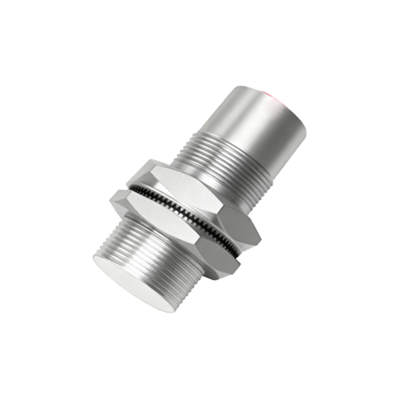
The nominal reset distance specified in a datasheet is measured under ideal, standardized conditions (e.g., a specific target material, size, and ambient temperature). In real-world applications, several factors can cause the actual reset distance to vary:
1. Target Material: Inductive sensors are calibrated for ferrous metals (like mild steel). Using aluminum, copper, or stainless steel will significantly reduce both the operating and reset distances. Capacitive sensors are affected by the material's dielectric constant.
2. Target Size and Shape: The target must meet the sensor's specified "standard target" size. A smaller target will reduce the effective sensing and reset distances.
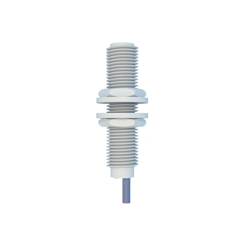
3. Supply Voltage: While modern sensors have good voltage tolerance, operating at the extreme ends of the specified voltage range can slightly affect switching points.
4. Temperature: Extreme ambient temperatures can affect the sensor's electronics and coil, causing drift in the sensing characteristics, including the reset distance.
5. Sensor Mounting: Installing the sensor flush in a metal bracket (for inductive types) is standard. Non-flush mounting or adjacent metal objects can influence the magnetic/electrical field, altering performance.
Practical Implications and Application Tips
Ignoring the reset distance can lead to system errors. Consider a robotic arm that places an item on a conveyor. A sensor confirms the item is in place before the arm retracts. If the arm's retraction path is programmed based only on the operating point, the sensor might still be "ON" during initial retraction, causing a logic conflict. The system must be programmed to acknowledge the reset event, confirming the arm has cleared the area.
Key Application Guidelines:
Always Consult the Datasheet: Manufacturers provide detailed graphs and specifications for operating and reset points relative to target material and size. The hysteresis value is often stated.
Design for the Reset Point: In sequencing logic, use the reset event as a positive confirmation that an object has left the detection zone. This is more reliable than assuming it has left after a timed delay.
Allow for Tolerance and Drift: Do not design your mechanical positioning to operate at the absolute theoretical reset distance. Include a safety margin (e.g., 20-30%) to account for sensor tolerance, wear, temperature effects, and mechanical misalignment over time.
Testing is Essential: After installation, physically verify the actual operating and reset distances with the exact target used in the application. This validates the entire mechanical setup.
Troubleshooting Reset Distance Issues
If a sensor appears to "stick" in the ON state or resets prematurely, consider these checks:
Target Characteristics: Verify the target material, size, and approach angle match the sensor's specifications.
Sensor Wear or Damage: The sensing face should be clean and undamaged. Physical impact can degrade performance.
Electrical Noise: Strong electromagnetic interference in industrial environments can sometimes affect sensor behavior. Ensure proper shielding and grounding.
Load Compatibility: Ensure the sensor's output is compatible with the connected load (e.g.,