Proximity sensors are essential components in modern industrial automation, providing non-contact detection of objects. Understanding the terminal connection diagram is crucial for proper installation, operation, and troubleshooting. This guide details the standard terminal configurations, wiring practices, and safety considerations for common proximity sensor types, including inductive, capacitive, and ultrasonic sensors.
A typical proximity sensor features three to four terminals, though some models may have more for advanced functions. The most common configuration includes:
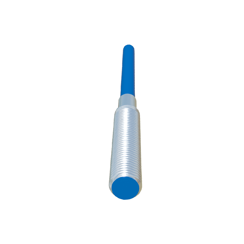
- Brown Wire (or L+): This is the positive supply terminal. It connects to the DC power source's positive line, typically ranging from 10-30V DC for standard sensors.
- Blue Wire (or N or L-): This is the negative supply terminal or common. It connects to the DC power source's negative line or ground.
- Black Wire (or OUT): This is the output signal terminal. In a normally open (NO) configuration, the black wire provides a switched positive voltage when an object is detected. In a sinking (NPN) or sourcing (PNP) output type, the wiring logic differs accordingly.
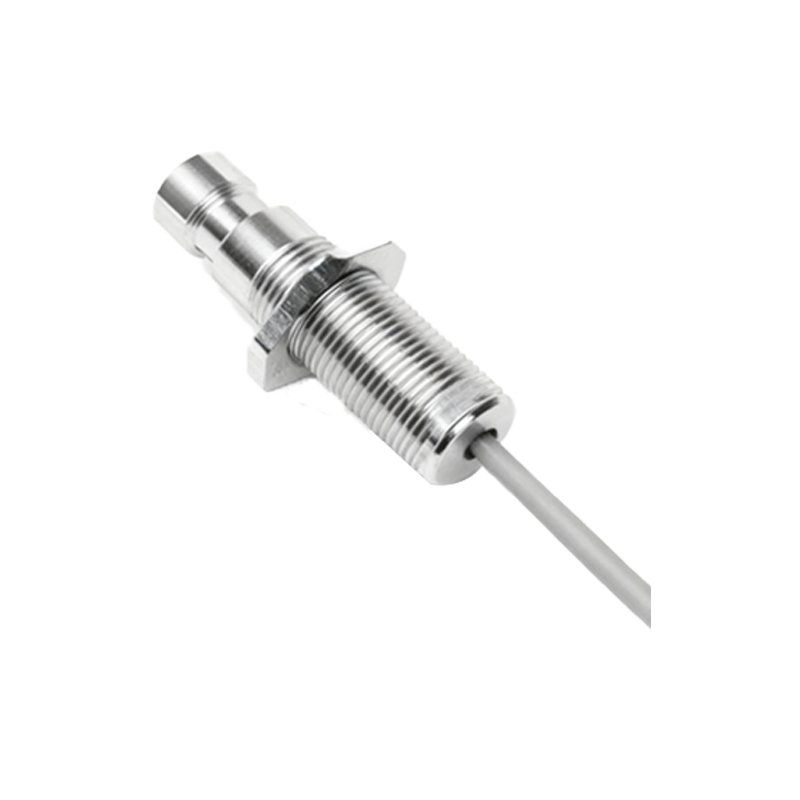
- White Wire (or OUT2): Often present in sensors with a complementary output or a second switching function. It may provide a normally closed (NC) signal or a separate output channel.
Terminal Diagram Interpretation:
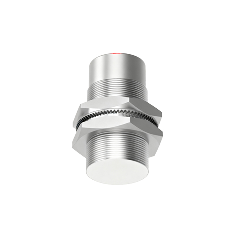
The terminal connection diagram, usually found on the sensor's label or datasheet, uses standard IEC symbols. A rectangle represents the sensor body. Terminal points are marked with abbreviations or colors. Lines indicate internal connections; for instance, a line from the brown terminal to the output switch inside the sensor, and from the switch to the black terminal. The load (e.g., a PLC input, relay, or indicator) is connected between the black output terminal and the blue terminal (for PNP) or between the black output and positive supply (for NPN).
Wiring Practices:
1. Power Supply: Always use a stabilized DC power supply within the sensor's rated voltage. Incorrect polarity can damage the sensor.
2. Output Loading: Do not exceed the maximum output current specified. For heavy loads, use an intermediate relay.
3. Shielding: In electrically noisy environments, use shielded cables. Connect the shield to ground at the control panel end only to prevent ground loops.
4. Wiring Separation: Keep sensor cables away from high-voltage power lines and motor cables to avoid inductive interference.
5. Waterproof Connectors: For washdown or outdoor applications, ensure connectors are properly sealed per IP ratings.
Safety and Compliance:
Always disconnect power before wiring. Follow local electrical codes and standards such as IEC 60947-5-2. For AC-powered sensors, additional terminals for neutral and ground may be present. Verify the sensor's output type (NPN vs. PNP) matches the input requirements of your controller. Incorrect matching can lead to malfunction or short circuits.
Troubleshooting Tips:
- No Output: Check power supply voltage and polarity at the terminals. Verify the sensing object is within range and of correct material.
- Intermittent Operation: Inspect for loose connections, cable damage, or external electromagnetic interference.
- Sensor Damaged: Ensure load current is not exceeded and there are no voltage spikes from inductive loads; use protective diodes or surge suppressors if needed.
Proper interpretation of the proximity sensor terminal diagram ensures reliable integration into control systems, minimizing downtime and enhancing operational safety. Always refer to the manufacturer's specific documentation for exact terminal designations and wiring instructions, as variations exist between models and brands.