In the realm of industrial automation and precision manufacturing, laser cutting stands as a pinnacle of accuracy and efficiency. At the heart of this sophisticated process lies a network of critical sensors, each playing a vital role in ensuring optimal performance, safety, and quality. This guide delves into the schematic representation of a typical laser cutting sensor system, breaking down its components and their interconnections for electrical engineers and industry professionals.
A standard laser cutting sensor schematic diagram can be conceptually divided into several key functional blocks: the laser source and beam delivery, the motion control system, the workpiece sensing and monitoring suite, and the central safety interlock network. Understanding the symbology and signal flow between these blocks is essential for system design, troubleshooting, and optimization.
Starting with the Laser Source Unit, the schematic will depict the high-power laser resonator (often a CO2, Fiber, or Nd:YAG laser). Critical sensors here include cooling water flow sensors and temperature sensors for the laser tube or gain medium. These are typically represented as flow meters (a circle with a diagonal arrow) and thermocouple symbols connected to a monitoring PLC (Programmable Logic Controller). Their signals ensure the laser operates within its specified thermal envelope, preventing damage.
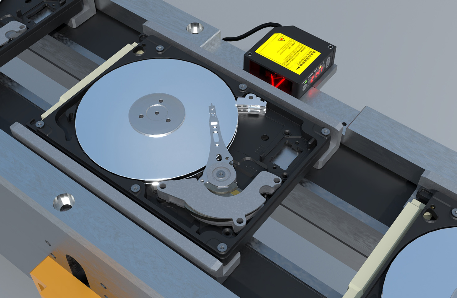
The Beam Delivery Path is monitored by beam diagnostic sensors. A schematic may show a beam profiler or power sensor symbol placed via a beam splitter in the optical path. This sensor provides feedback to the laser power supply, creating a closed-loop control system to maintain consistent cutting power. Any deviation from the setpoint can trigger an alarm or automatic shutdown.
The Motion Control System is integral. The schematic details servo or stepper motors driving the X, Y, and Z axes. Key sensors here are high-precision linear encoders (represented as a rectangular block with pulse output lines) and limit switches (normally open or closed contact symbols). The encoders provide real-time positional feedback to the motion controller, ensuring the cutting head follows the programmed path with micron-level accuracy. Limit switches define the physical boundaries of the machine, preventing over-travel collisions.
Perhaps the most critical for process quality is the Workpiece Sensing and Monitoring Suite. This includes:
1. Capacitive or Inductive Height Sensors: Symbolized as a probe-like shape, these sensors are mounted on the cutting head. They continuously measure the distance to the workpiece surface, providing feedback to the Z-axis servo to maintain the optimal focal point standoff distance, crucial for cut quality.
2. Pierce Detection Sensors: Often optical or acoustic, these detect the moment the laser pierces through the material. This signal is fed back to the CNC to initiate the main cutting path, preventing defects at the start point.
3. Cutting Head Temperature Sensors: Embedded near the nozzle, these thermistors monitor for excessive heat buildup from spatter or collisions.
4. Nozzle Contact Sensors: These are simple mechanical or capacitive sensors that detect physical contact between the cutting nozzle and the workpiece, immediately halting motion to prevent damage.
The Safety Interlock Network is the system's nervous system, represented by a series of normally closed contacts in series. This network integrates door safety switches (on access panels), emergency stop buttons, light curtains, and gas pressure sensors (for assist gases like Oxygen or Nitrogen). A break in any of these interlock circuits, indicated by a change in the sensor's state, will immediately disable the laser high voltage and halt all drives, ensuring operator and machine safety.
The schematic illustrates how all these discrete sensor signals converge into the main Machine Control PLC or Industrial PC. Analog signals (4-20mA or 0-10V) from temperature, pressure, and analog distance sensors are wired to analog input modules. Digital signals from encoders, limit switches, and proximity sensors are connected to high-speed digital input cards. The PLC logic, not shown in the schematic but implied, processes this data, making real-time decisions to adjust parameters or initiate safety sequences.
In modern systems, fieldbus or Industrial Ethernet symbols (like PROFINET, EtherCAT, or EtherNet/IP connectors) are increasingly common, showing digital sensor networks where multiple smart sensors communicate data over a single cable, reducing wiring complexity.
For an electrical engineer, interpreting this schematic involves tracing signal paths from sensor to controller, understanding the power requirements (often 24VDC for industrial sensors), and recognizing the grounding and shielding practices indicated to mitigate electrical noise, which is paramount for the low-voltage signals from precision encoders and analog sensors. A well-drawn schematic is not just a wiring diagram; it is a blueprint for system integrity, reliability, and precision in the demanding environment of laser cutting.