Assembling a laser displacement sensor might seem daunting, but with the right approach and attention to detail, it can be a straightforward process. This guide walks you through the essential steps, from unpacking components to final calibration, ensuring your sensor operates with optimal accuracy and reliability.
Before starting, gather all necessary tools and components. A typical laser displacement sensor kit includes the sensor head, controller unit, mounting bracket, power supply cables, and communication cables (such as Ethernet or USB). Ensure you have a clean, static-free workspace to prevent damage to sensitive electronic parts.
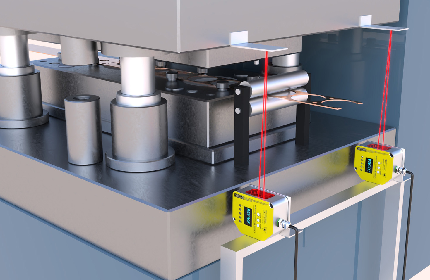
Begin by inspecting all components for any visible damage incurred during shipping. Check the sensor lens for dust or scratches, as even minor imperfections can affect measurement precision. Next, mount the sensor head securely using the provided bracket. Position it so that the laser beam aligns perpendicularly to the target surface, as angular misalignment can lead to measurement errors. Tighten the mounting screws firmly but avoid over-tightening, which might strain the housing.
Connect the sensor head to the controller unit using the designated cable. Most modern sensors use standardized connectors, but always refer to the manufacturer's manual for specific wiring diagrams. Ensure connections are snug to prevent signal interference. Then, link the controller to your power supply, adhering to voltage specifications—typically 12-24V DC for industrial sensors. Incorrect power input can cause permanent damage.
Once powered, proceed with the initial setup via the sensor's software interface. Many sensors come with proprietary configuration software that allows you to adjust parameters like sampling rate, output format, and measurement range. Calibrate the sensor using a known reference target, such as a calibration plate or gauge block. Follow the on-screen prompts to set zero points and linearity, which are critical for accurate displacement readings.
Testing is a crucial phase. Place a test object within the sensor's measurement range and observe the output on the software or connected display. Verify that readings are stable and correspond to the actual distance. If discrepancies occur, recheck alignment and calibration settings. Environmental factors like ambient light or vibrations can also impact performance, so consider installing protective housings or filters if operating in harsh conditions.
Finally, integrate the sensor into your larger system, whether it's a quality control line, robotic arm, or research setup. Ensure all communication protocols (e.g., Modbus, PROFINET) are correctly configured for seamless data transmission. Document your assembly steps and settings for future maintenance or troubleshooting.
Regular maintenance, such as cleaning the lens with a soft cloth and checking cable integrity, will prolong the sensor's lifespan. By following these steps meticulously, you can achieve reliable, high-precision measurements essential for applications in manufacturing, automation, and metrology. Remember, patience and precision during assembly pay off in long-term performance.