In industrial automation systems, metal proximity sensors are indispensable components for non-contact detection of metallic objects. Their integration into a Programmable Logic Controller (PLC) system is fundamental for creating responsive and reliable control sequences. This article delves into the standard wiring configurations and schematic representations found in PLC diagrams for these ubiquitous sensors.
Firstly, it is crucial to distinguish between the two primary types of metal proximity sensors relevant to PLC interfacing: the 3-wire DC sensor and the 2-wire AC/DC sensor. The 3-wire DC sensor is the most common in modern PLC applications. Its wiring diagram typically shows three distinct wires: brown (or red) for the positive DC supply voltage (often +24V DC), blue for the common negative or 0V DC, and black (or white) for the switched output signal. This output can be either PNP (sourcing) or NPN (sinking). A PNP sensor switches the positive voltage to the PLC input, meaning the black wire connects to the PLC digital input module, and the PLC input's common is connected to 0V. Conversely, an NPN sensor switches the negative or 0V line to the PLC input, requiring the PLC input common to be connected to +24V. Misinterpreting this PNP/NPN distinction is a common wiring error that prevents proper operation.
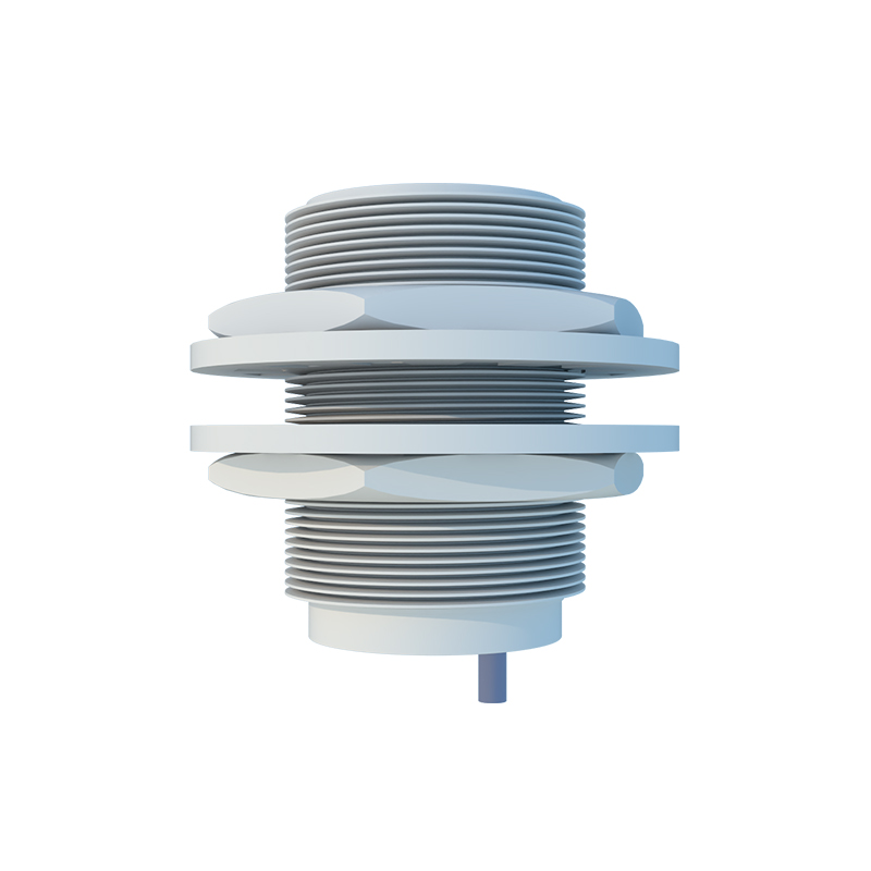
The PLC diagram symbol for a proximity sensor is usually a simple switch or a diamond-shaped icon with a sensing field indicator, labeled with a part number like "PRX1". The accompanying ladder logic representation is straightforward. When the sensor detects a metal target, its internal switch closes (or opens, depending on the configuration), completing the circuit to the assigned PLC input point (e.g., I0.0). This change in state from FALSE to TRUE is read by the PLC's processor on every scan cycle.
For a 3-wire sensor, the typical PLC wiring diagram shows the +24V DC power supply from the PLC rack or an external source connected to the sensor's brown wire. The blue wire is connected to the 0V DC of the same supply. The sensor's black output wire is connected to one terminal of the PLC digital input card. The other side of that PLC input channel is internally connected to the input card's common, which must be wired correctly to match the sensor type. For a PNP sensor, this common is tied to 0V. The diagram must clearly show this loop: Power Supply (+) -> Sensor Brown -> Sensor Internal Circuit -> Sensor Black -> PLC Input I0.0 -> PLC Input Common (0V) -> Power Supply (-).
Two-wire AC sensors, often used in older or high-power applications, are wired in series with the load (the PLC input). They do not have a separate supply wire. In a diagram, one wire connects to the AC line (e.g., L1), and the other wire connects directly to the PLC input. The PLC input's other terminal connects to the neutral (N). It is vital to ensure the sensor's leakage current, when in the "OFF" state, is below the PLC input's minimum "OFF" current threshold to avoid false triggering.
Shielding and grounding are critical elements often detailed in professional PLC diagrams. A shielded cable is recommended for sensors in electrically noisy environments. The diagram should indicate that the cable shield is grounded at one end only, typically at the PLC cabinet's ground bus bar, not at the sensor end, to prevent ground loops.
Practical considerations in the diagram include fusing for the sensor power lines, often a 2A or 3A fuse for a bank of sensors. Diagnostic indicators are also shown; most sensors have an LED that lights when active. In the ladder logic, engineers often create diagnostic routines using the sensor's input bit to trigger an alarm if a target is detected for too long (indicating a jam) or not detected within an expected time window (indicating a missing part).
In conclusion, correctly interpreting and implementing the PLC wiring diagram for a metal proximity sensor is a foundational skill. It requires attention to the sensor type (PNP/NPN, 3-wire/2-wire), proper sourcing of the power supply, accurate connection to the PLC input module's common, and adherence to best practices for shielding. A well-drawn diagram serves as the blueprint for a stable interface, ensuring the sensor reliably informs the PLC's control logic, forming the backbone of automated sequencing, counting, and positioning tasks in machinery and conveyor systems.